
Tuning Weber Carbs
Written by Tom Jennings, edited by Frank Swygert 01-30-2026
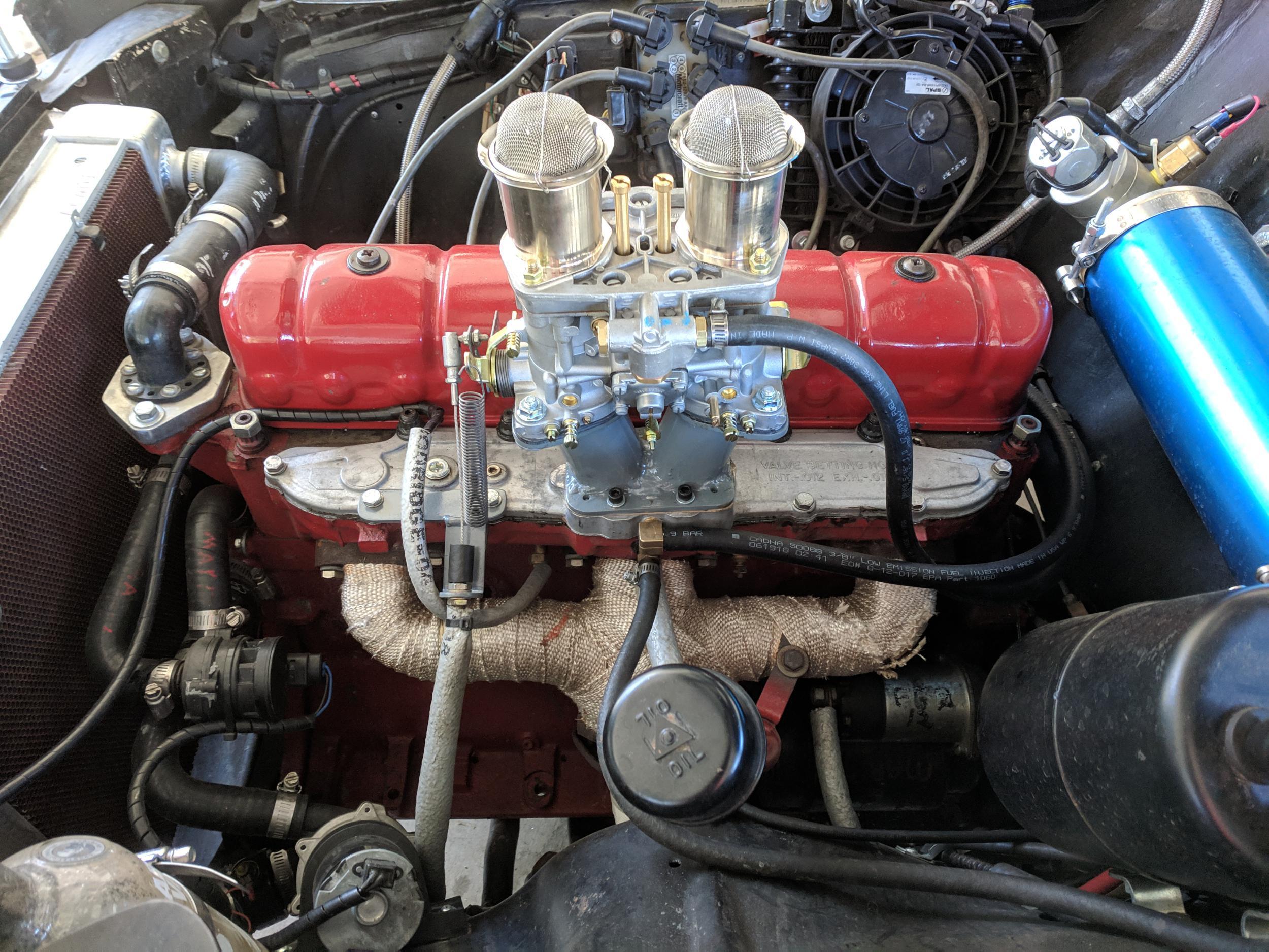
Tuning a 44 IDF for the Rambler 195.6 OHV (3200cc) inline six. Most also applies to other Webers like the 32/36 DGEV and 38/38 DGES.
reference: Top End Performance, highly recommended by me.
reference: Redline/Weber IDF adjustments
reference: Weber float level
reference: Weber factory tuning manual (the final word, as disorganized as it is)
reference: VM flat-four, but many useful ideas and tips
reference: 240 260 280 weber tuning
reference: SAFRtool.com, target A/F ratio values
reference: Innovate Motorsports, relationship between spark advance and fuel mix
reference: Rambler 195.6 OHV inline six
Below I describe how my experience differed from “standard advice” found elsewhere. RTFM first, then this. I assume you know how a carburetor works and can figure out how to setup a Weber.
The final authority on Weber carburetor operation and tuning is the factory manual above.
Old inline motors are not sports car motors
Older american-type inline sixes like ours differ from european sports cars
in how they meet their design goals. There are some terminology differences
too. Though this written specifically for my warmed-over Rambler 195.6 OHV,
this would apply to small Ford Chevrolet and Dodge/Chrysler engines of the 50s,
60s and 70s.
The common sports-car application is one or two venturi per cylinder. The
path from throttle plate to intake valve is short. Most sports-cars are
oversquare, have relatively hot cams that accentuate intake pulsing. Most
carbureted sports cars seem to have no PCV or other air-injecting accessories.
While RPMs are higher the volume of air drawn per-stroke is lower.
In contrast my engine, like a lot of 50’s and 60’s american inlines, is
undersquare, six cylinders, and has a very mild cam. All cylinders are
manifolded to a single carb. The fuel/air intake is likely considered to be a
“flow” (it’s still bumpy, but less so) and manifolding, mild cam and long
stroke means the carb sees a much stronger, smoother draw through the venturi.
RPM range is lower than sports-engines so the rules of thumb built into
standard advice (“main jet operation begins at XXXX RPM”) is often just plain
wrong.
These differences manifest in tuning details, in progression circuit(s)
operation, and the resulting state of tune.
DESIRED STATE OF TUNE
This info is all over the place, but I found this nice summary from SAFR tool, succinct and to
the point. Here is a copy of TARGETING AFR
VALUES in case that page goes away. Note that the IDF series don’t
have high speed enrichment eg. power valves; they are assumed to be for
performance use and so are always set somewhat rich. A better way to think of
the IDFs and DCOEs is that they lack “economy” circuits. And they don’t
generally have chokes.
Spark timing
MEASURING AIR/FUEL RATIO
I have an Autometer in-dash A/F ratio meter installed. Tuning by ear and the
seat of your pants is still important, but I now can’t imagine tuning without
an A/F meter. Best $200 i ever spent. I have a homemade datalogger system and
it reads the analog voltage off the meter and stores it as AFR once per second.
I have found that the meter is required for highway cruise jetting. For low
speed and acceleration/WOT, it jives with by-ear and seat-of-the-pants where so
far it seems to want one-jet richer than what the meter says, which also fits
with general carb advice for other engines.
BRAND NEW OUT OF THE BOX, CHECK THESE THINGS FIRST
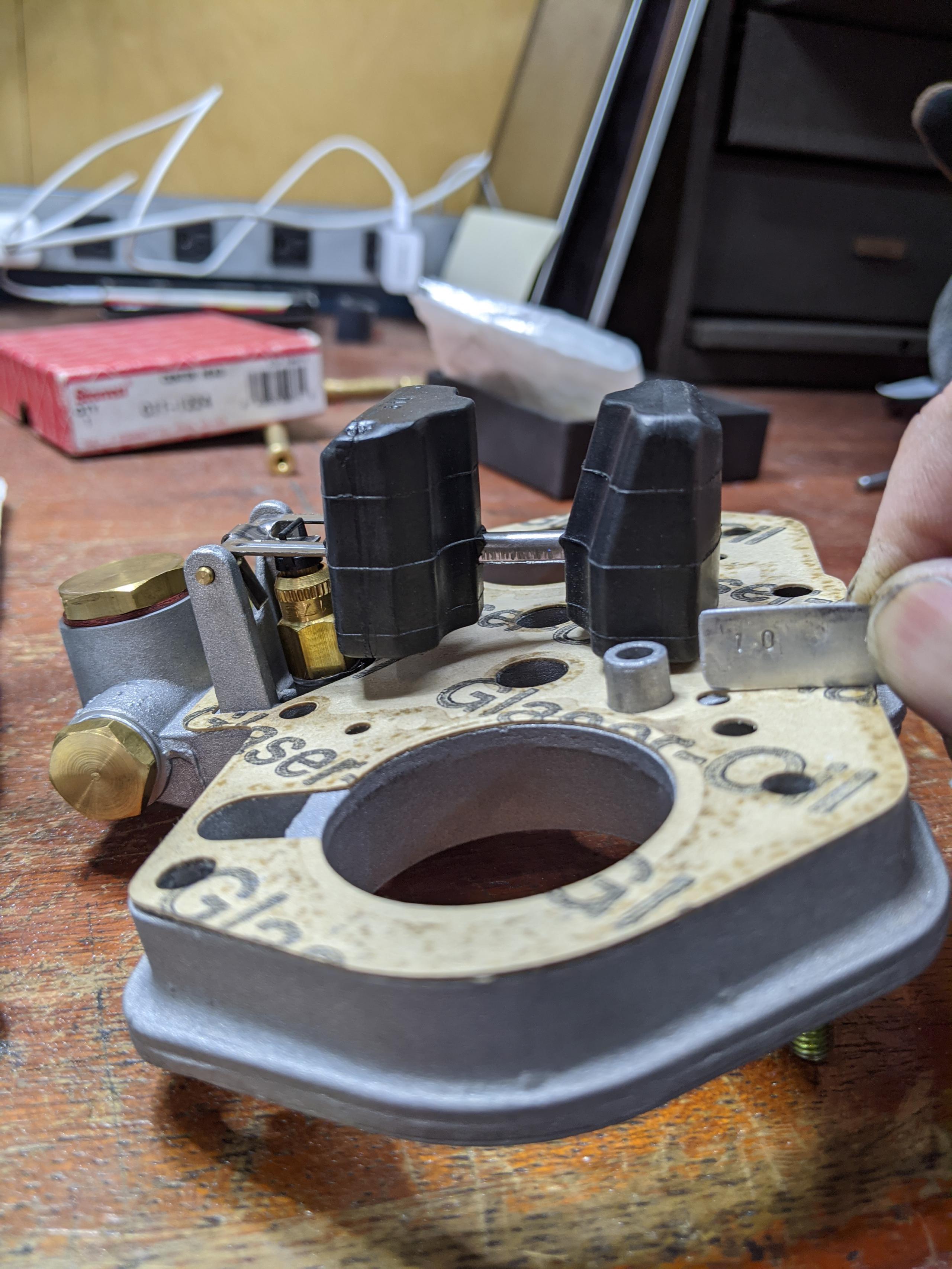
Set float level first!
First thing, take the top off and set the float level. I have not yet had
one Weber carburetor with the float level set even approximately
correct out-of-the-box. My 44IDF was supposed to be 10mm and it was more like
5mm. The 40 IDF… well see for yourself, below. The float is resting on the
gasket (float is set with the carb top vertical).
Adjustment requires some care as the tabs you have to bend are small and
stiff and attached to delicate plastic floats so you pretty much have to pull
the pin, bend, reassemble, check, remove, repeat, ad nauseum. While you’re in
there verify what jets are actually installed, including the
squirter return jet.
I made tools from a pieces of aluminum sheet; cut and filed to exactly 10mm
and 32mm high, used as a feeler gauge.
Fuel pressure
American cars of a certain era have mechanical pumps that deliver 5 – 7 psi.
This is too much for Webers that want 3 – 4 psi. I run a Carter P60504 electric
(vane) pump. They’re cheap and work great. Put a filter on the inlet to the
pump, grit will ruin it. OEM diaphragm pumps are happy pulling fuel; electrics
push. pulling (often, air) will burn up the pump. Put the pump out back and,
best, low, so gravity primes it.
My tuning experience

The above is a pretty great chart, found on at the 240/260/280 Z website
listed above. Where it says “RPM” think “relative air mass flow” (there’s that
sports-car-engine assumption). As flow increases from idle to maximum, the
contribution of fuel from each circuit — idle mix screws, low speed jets, main
jets — changes. The crossover can be quite distinct.
the chart is just a rough guide, and it understates the effect of the idle
mixture which affects much “low speed” driving.
Weber carbs are tuned one circuit at a time; idle, progression, and only
then, main jets/air jets. Carburetor tuning is necessarily iterative; make it
idle, determine low speed jet, then high speed jets, and chances are you will
be back to revisit idle and progression again, especially new-out-of-the-box.
STEP 1: Curb idle
The first thing to do is to get it to idle. Start with idle screws 1.5 – 2
turns out from bottomed (likely rich). Back off the idle speed screw (throttle
stop) until it doesn’t touch, then turn it in 1 to 1.5 turns. Start the engine,
blip the throttle as necessary to get it warm enough to idle. Unless you have
a big vacuum leak this will idle, even with wrong low speed jets. It might run
for shit but it will run.
The idle speed and mixure adjustments interact and require iterating. Set
speed with the speed (throttle stop) screw, then adjust idle mixture screws
(both out exactly the same amount) for fastest idle. If it speeds up too much
adjust the throttle stop screw, repeat mixture adjustments until it’s perfect.
These are initial settings, you’ll probably want it slightly richer for
driving.
STEP 2: Progression A/F ratio
With a candidate pair of low speed jets, engine warmed up, adjust best idle
speed and smoothness as above.
You need to know the range of throttle opening over which the progression
circuit is controlling A/F ratio. The range begins when the throttle plate
begins to open, and ends when flow is sufficient to pull fuel from the booster
venturi. See the paragraph below on how to determine this range.
With a wideband A/F meter
The process is very straightforward with a wideband A/F meter.
- Turn the throttle stop screw in “until the first progression hole
is uncovered”, probably 3.5 turns (see photos below). The
engine is now running on the progression circuit. - The low speed jets are now the sole determining factor of A/F
ratio. I tune for 13:1 here; swap low speed jets until you get
what you want.
If you change low speed jets you will need to redo curb idle settings.
Without a wideband A/F meter
Without a wideband meter, this method is based upon “standard advice”. The curb
idle is first adjusted for ideal idle, then the actual mixture in the progression
circuit is compared to it.
- Set curb idle to desired speed (throttle stop speed screw) then for
the highest smooth idle speed using the mixture screws. For
driving you’ll probably want a slightly richer mix. - Now turn the throttle stop screw in “until the first progression
hole is uncovered”, probably 3.5 turns (see photos below). The
engine is now running on the progression circuit. - Perform these simple tests:
- Turn both idle mixture screws in (lean) 1/4 to 1/2 turn each.
If idle RPM increases, your low speed jet is too rich (too
large). - Turn both idle mixture screws out (rich) 1/4 to 1/2 turn each.
If idle RPM increases, your low speed jet is too lean (too
small). - If turning the mixture screws in either direction worsens
idle speed, your low speed jets are correct.
If you change low speed jets you will need to redo curb idle settings.
This non-wideband meter method is taken directly from the Weber
factory tuning manual page 43 and conforms to all information in
the Weber factory manual. It is critical that the progression circuit mix be
correct, and the only way to adjust it is with the low speed jet. With the
progression circuit correct, you can always get curb idle mix right by turning
the idle mixture screws.
Observations on idle mixture screws settings
Redline documentation dogmatically insists that idle mixture screws must be
exactly one turn out; there is no such rule in the factory tuning manual. It is
true however that the mixture screws will end up approximately one turn
out once you have selected the low speed jets based upon their behavior in the
progression circuit.
Standard advice does not account for the air added by PCV systems. Even
with wrong low speed jets you can make the engine idle correctly by fiddling
the idle mixture screws.
If you get progression right, but the idle mix screws are less than one turn
out, you have some unwanted source of fuel; did you set the floats right? If
the mixture screws are out two or more turns, eg. adding a lot of fuel to idle,
you probably have a vacuum leak somewhere.
How to locate the progression/main circuit transition
Imagine the car on a long straight flat road. Engine running, put it in
gear, smoothly open the throttle and accelerate up to maximum speed. The
throttle goes from closed (“curb idle”) the idle circuit, through the
progression circuit, into the main jets.
The chance of an out-of-the-box Weber doing this smoothly and at desired A/F
ratio is zero.
The first step to tuning is to figure out which circuit is operating when.
The idle circuit to progression circuit was tuned by the procedure above.
With an IDF series carb it’s incredibly easy — remove the two jet/emulsion
tube assemblies from the carburetor. The carb will then have only idle and
progression, and a huge dead lean hole above that. The VW flat-four page above
suggested this and it works great. This does throw off the the progression
circuit’s A/F ratio (leans it out) so you might have to go up one low-speed jet
size just for this test. But it’s worth the effort — a half hour’s drive
without main jets will provide you with a feel for where progression ends and
main jets begin. I assume the same is true with DCOEs.
For the 32/36 and 38/38, or the IDF, another method is to install crazy-lean
jets to get the same effect. It’s much easier to feel too-lean (bog, engine
dies) than too-rich (feels “soft”). An A/F meter helps here, but a too-lean jet
will provide the same feel as the above IDF-no-jet.
Work in progress
STEP 3: Main jets, air jets
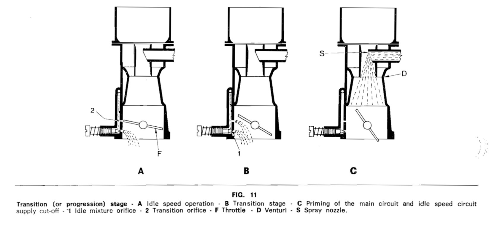
The flatspot: idle transition holes
With the throttle closed (idle position) the edge of the throttle
plate must just block the first transition hole. Off-idle
flatspot/bog is caused by the throttle plate being below the transition holes.
i don’t know what engine will end up with them magically in the right place but
mine wasn’t one of them. (engines that need more throttle plate opening at
idle, which would then uncover transition hole(s) is another set of symptoms
and fixes that I did not experience. this is also covered in the weber manual.)
My engine idles at 500 rpm with the idle speed/throttle stop screw 1/2 turn
in, which leaves the throttle plate below the first transition hole, creating a
brief but sharp flatspot immediately off-idle. The only cure for this is to
file a bevel in the edge of the throttle plate; see the procedure below.
this drawing from page 10 of the factory manual is illuminating:
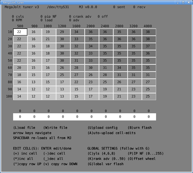
my current state of tune
This is the current (april 2019) snapshot of the state of tune. carb, spark,
axle, gears, chassis, usage, etc are all tangled together in a
multi-dimensional space.
Carburetor
Current state of tune, Los Angeles, sea level.
| 40 IDF, venturi | 28mm |
| low speed jets | 50 |
| idle stop screw | 1/2 turn |
| idle mix screws | 1.5 turns out |
| accelerator pump adj nut | 0.400″ in |
| main jets | 170 |
| air bleeds | 150 |
| float level | 10mm |
Spark
Spark advance is entangled with carb tune. Pinging (mild
detonation; too much spark advance) can be “cured” with excessively rich
mixture, and conversely, a rich mixture allows more spark advance than would be
possible with a truly correct mixture. for years I persisted with the “maximum
spark advance” myth, described very nicely here in Innovate Motorsports’ relationship
between spark advance and fuel mix.
Working with the A/F meter resolved this for me. as I got my cruise mixtures
more correct it got pingy with my high-advance spark map. To separate carb
jetting from spark timing issues I installed very conservative spark timing (5
– 10 degrees less at all load/rpm) and continued with carb tuning. Only when
jetting was correct/close did I work on spark timing — and found that far less
advance was required for maximum power.
Gearing
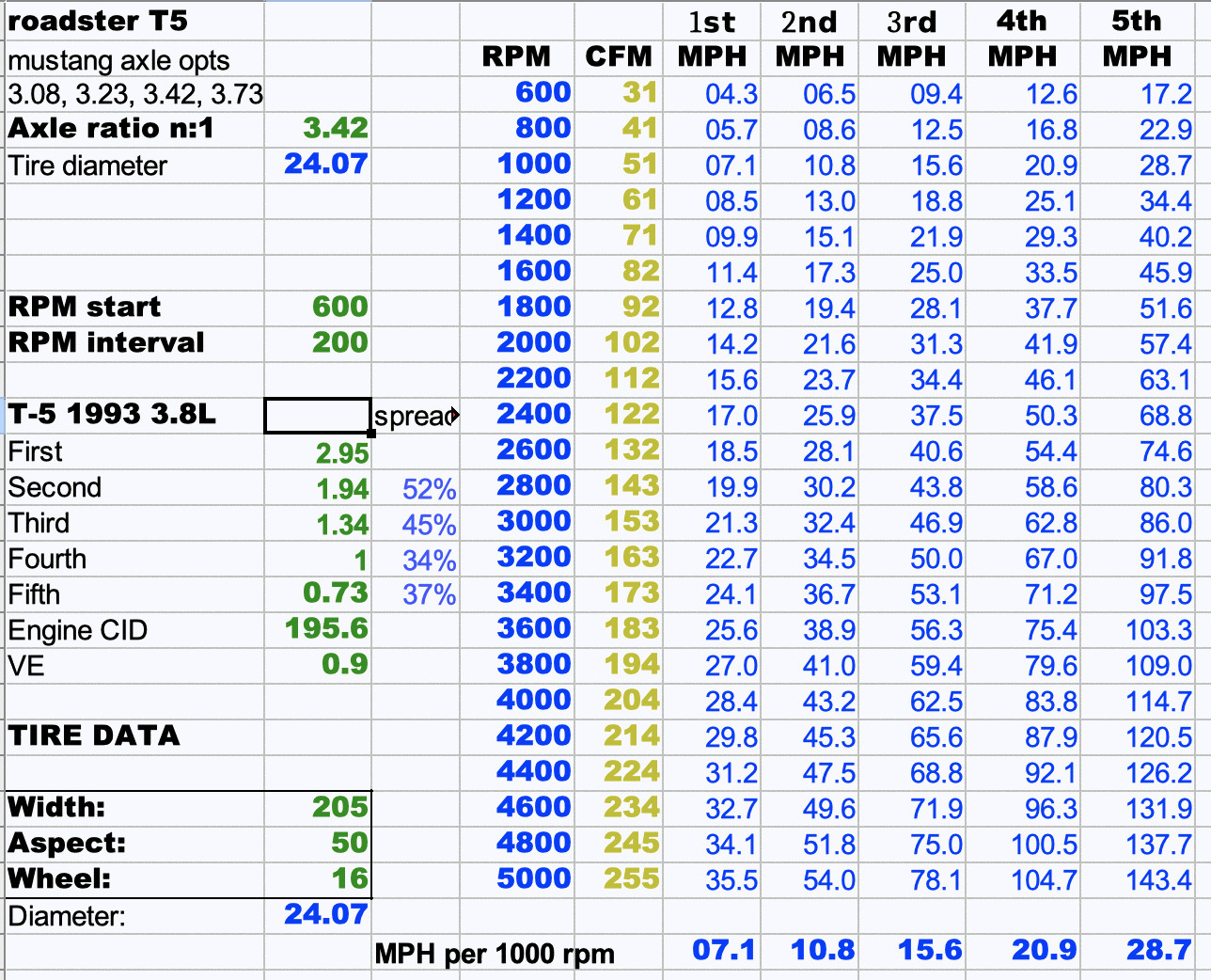
I make and maintain one of these spreadsheets for every car I make. The
Excel file is on my website somewhere. gear, tire, engine tell me RPM which
tells me where I need to tune. I used this to choose the axle ratio for my
cruise speeds and driving habits and prior experience with this engine.
i used this spreadsheet to choose axle and tire to match what I thought
the engine was happy with. now, After my experience with this 44 IDF and
spark changes, I plan on regearing to 3.73.
Throttle plate and transition holes
Correcting off-idle flatspot
With all circuits tuned fairly closely, I finally got around to working on
the off-idle flatspot. in my case this is caused by the idle stop screw
position required for correct idle speed and mix: 550 rpm at 14:1 mix, which
puts the throttle plate below the transition holes, so that throttle
tip-in increases air flow, but not fuel flow, causing the lean stumble.
The fix for this particular condition is to file the edge of the throttle
plate where it interacts with the transition holes. This procedure is in the
Weber factory manual. clearly it’s a last-resort fix, if you remove too much
metal, replacing throttle plates is no small deal.
The drawings in the manual are misleading in how much material must be
removed: it is far, far, much less than the drawings implied. lucky for me I
tend towards extreme conservatism when modifying delicate and expensive
objects.
I removed metal using 10 strokes of a fine, and dull, needle file
in the tiny area over the transition holes. I did not photograph the result
because the change is not visible.
below are photos of how I visualized the problem. Here the carb was removed
after tuning, with the idle speed stop set at it’s desired half-turn in. I
made two reference black spots with a marker and with a fine mechanical pencil
traced the edge of the closed throttle plate. Opened here to show the
relationship of throttle to holes.
| Closed, pencil mark drawn |
|---|
 |
| Open, pencil mark visible |
 |
There are two pencil marks, the one closer to the hole (lower in the photo)
is with idle stop in 1/2 turn; the higher one is with throttle completely
closed, for visual reference. As you can see the scale of things here is very
small and effects of tiny changes subtle.
The first transition hole edge was less than a millimeter from the bottom
edge of the throttle plate. Make sure you click the image above, then again to
get highest resolution to see the scale of things. I took the aforementioned
10 strokes off that trailing edge. It nearly, but not quite, eliminated the
dead spot. It will take one more iteration to get it “close enough”.
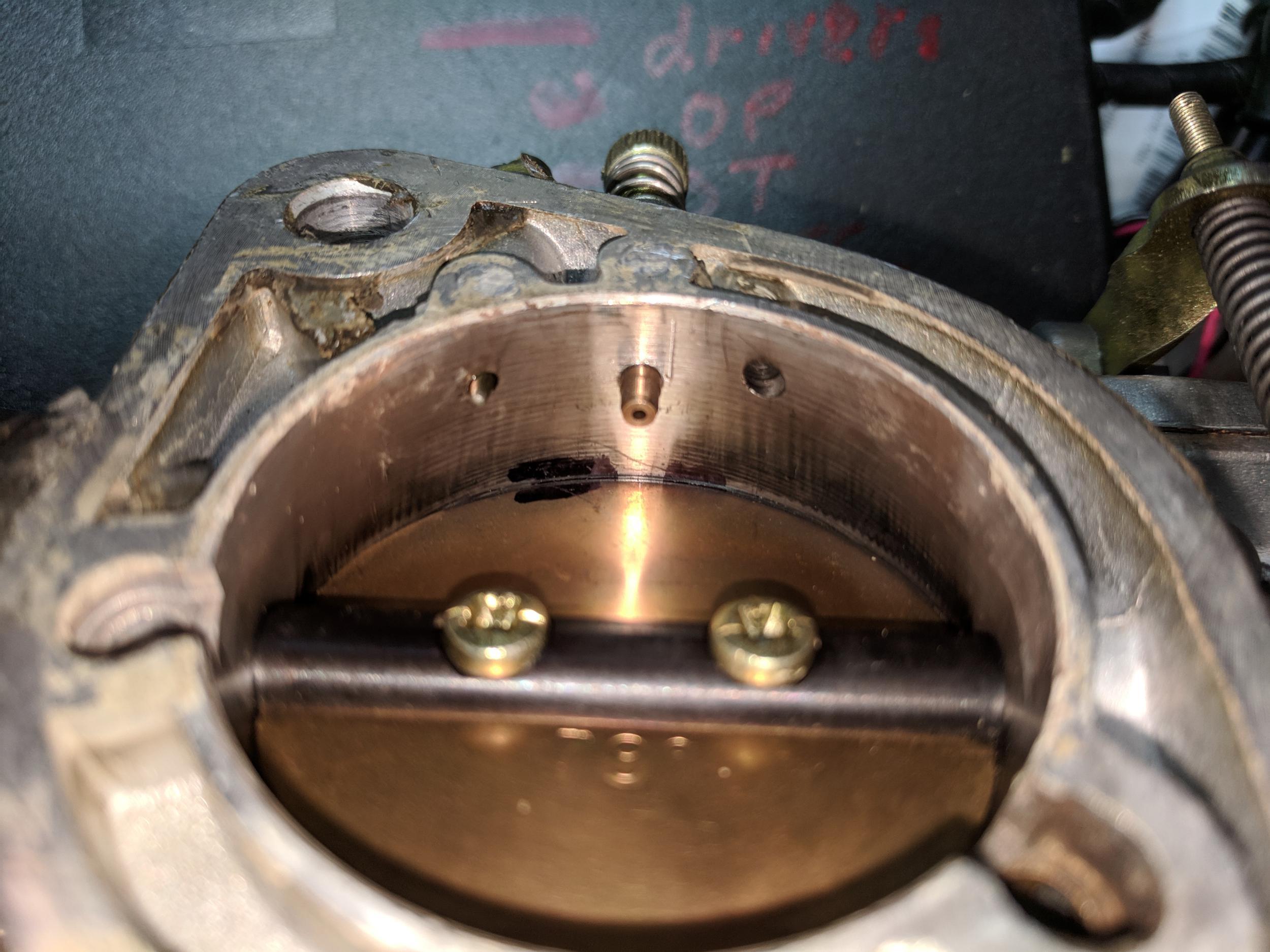
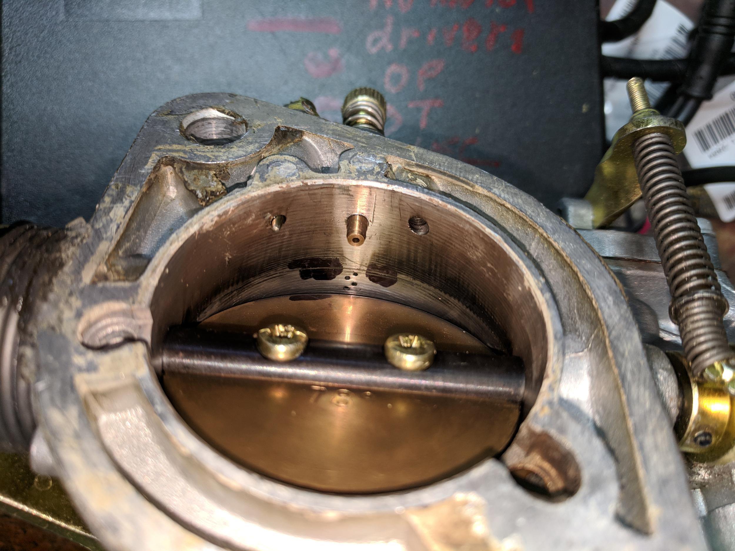
Throttle plate, transition hole relatioships made visible
The photos below show the relationship of throttle plate and transition
holes.
If you look carefully at the high-resolution photos below (click each image)
around 1 turn open the throttle plate is barely cracked open, about .010″ gap
perpendicular to the shaft. At about 2 turns open the edge of the first
transition hole becomes visible. The flatspot occurs because as the throttle is
opened, the crack opens to leak more air but the transition hole isn’t
uncovered until later opening.
The last photo shows all of the transition holes in the 44IDF, the throttle
opened by hand.
As a measure of how much air the PCV system injects, after plugging the PCV
the idle stop screw must be turned in (open) one-quarter turn more.
| Idle stop screw, turns in | (arrow points to where transition holes appear) |
| .75 turn |  |
| 1 turn |  |
| 1.5 turns |  |
| 2 turns |  |
| 2.5 turns |  |
| 3 turns |  |
| 3.5 turns |  |
| 4 turns |  |
| “many” |  |
Here’s why you buy a real Weber, made in Spain. A lot of the cheap eBay
clones look OK, but are often not very precise. and carburetors need to be
extremely precise. This 44IDF from racetep.com shows how nicely the
critical alignment of throttle plates vs. transition holes align. This means a
precise relationship between: throttle shaft bore in the body, throttle shaft,
the very precise position of the plates in the shaft, the bores of the tiny
(half millimeter) transition holes, all working in concert.
| idle stop screw 2.5 turns in after contact |
| left bore |
|
| right bore |
 |
Deprecated: File Theme without comments.php is deprecated since version 3.0.0 with no alternative available. Please include a comments.php template in your theme. in /home3/amcmagc1/public_html/wp-includes/functions.php on line 6114
Leave a Reply