
Rambler Classic, Ambassador 1962-1967 front suspension trickery
19 jan 2021
new 2005
This information is intended to help assemble or diagnose Rambler trunnion
front suspensions, and assumes you have a factory Technical Service Manual
(TSM) or you’re just winging it (heh heh) and that you have basic mechanical
competence. This isn’t a how-to for beginners. Though it’s specifically for a
1963-1964 Ambassadors or Classics it applies in general to all of the “big
chassis” cars (eg. 10, 80 series) until the 1970’s when they switched to a
ball joint on the upper arm.
All of the photos and procedures were worked out on my 1963 Classic wagon.
It was stock except as noted here.
There is a separate document for the
early Ramber American suspension.
While most manufacturers had switched to ball joints by the 1950’s, even,
Rambler hung on to them for a long time; maybe they had a barn full of the
things out back. Trunnions work well; even poorly maintained they last nearly
forever (at the time of this writing mine are 40 years old and still in fine
condition) but are subtle to install, and the information is
not in the technical service manual.
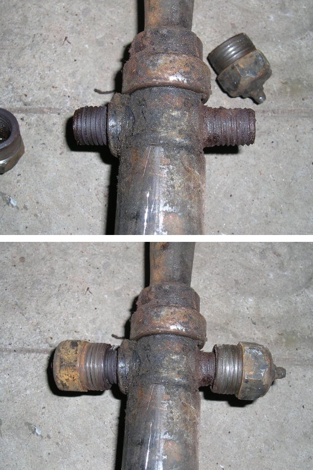
(Though they do require some maintenance! They’re not magic! Wayne
Lamothe inherited a ’63 Classic that someone had managed to apparently
never grease. It takes a close look to see that the threads on the
trunnion are worn down to where the cap simply slides off! (The driver was
never in any danger as the arms with spacer holds the assembly together by
itself.)
The Rambler front suspension works great — when i good condition.
Technically sweet, strong, very light, and you can bolt 1980’s disk brakes to
it. Once you have them sorted out, they work great, last a long time and are
reliable. Mostly people whine about them because they don’t understand them.
The two big gotchas with this suspension are:
- Upper trunnion assembly is tricky to do right;
- Lower control arm strut bushings are unavailable for the earliest years.
I’ve worked out safe and repeatable solutions to these problems. Each has a
section below.
Component inspection and preparation
I strongly suggest thoroughly cleaning all of the suspension components.
You will not get the trunnion assembly process right if the parts are encrusted
with old grease and grit. It is not easy to get all the hardened grease and
dirt out.
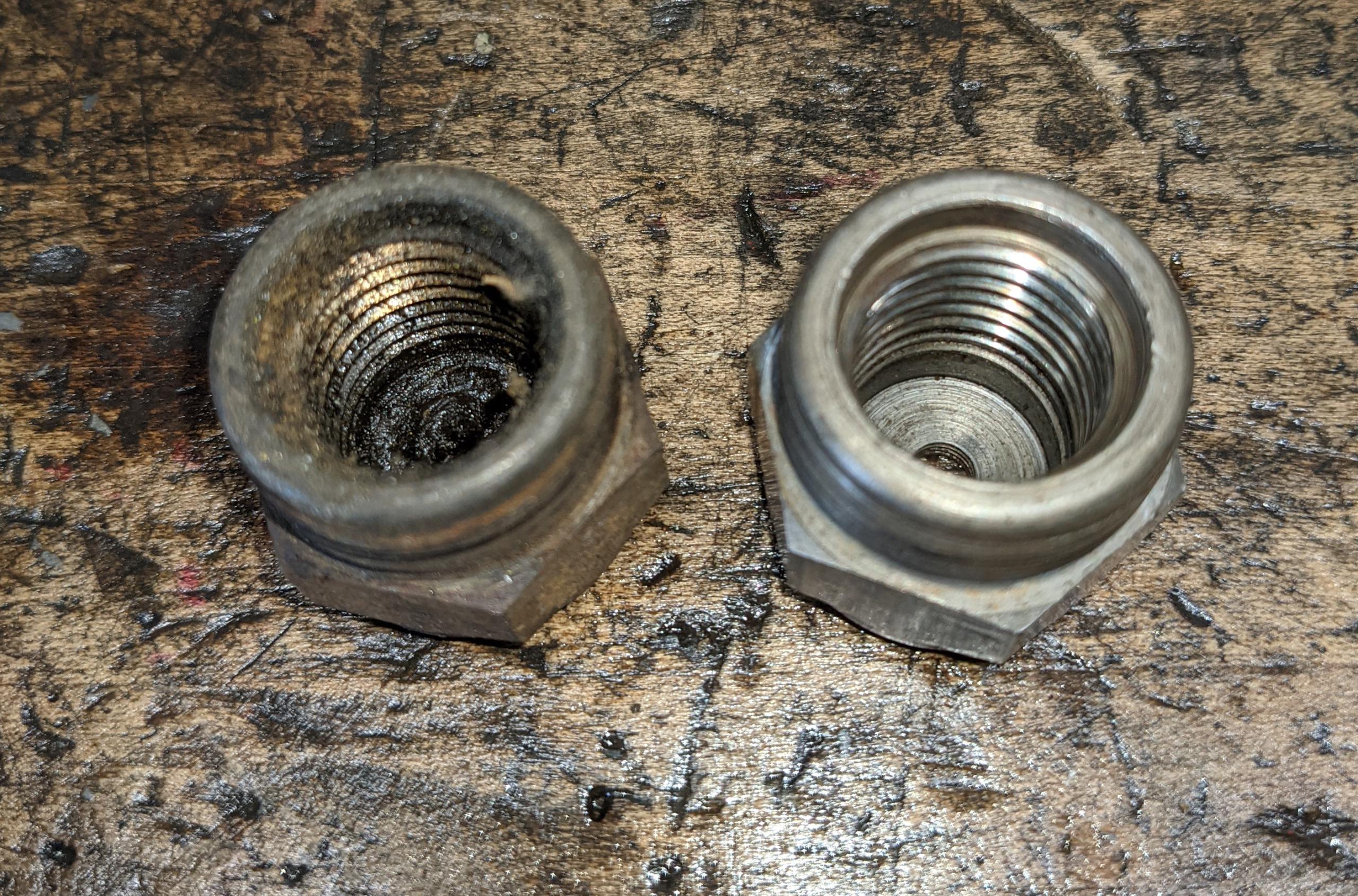
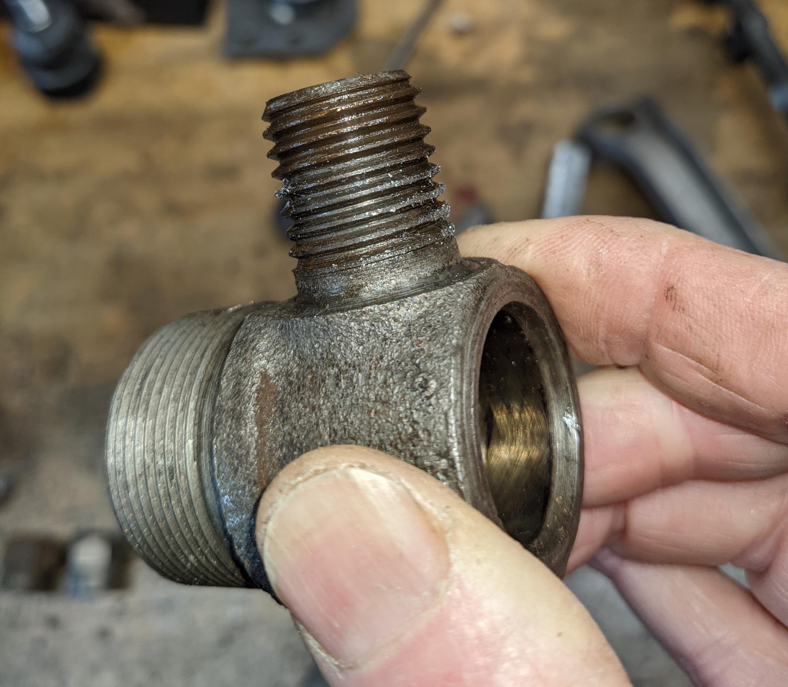
The procedure below requires the trunnion cap insides to be
completely free of old grease and grit. You will probably have to pick it out
with a sharp tool, wash in solvent, and repeat more than once. In the how-to
sequence below the “dirty” parts below we tight enough to torque loose the cap
from the arm. It must turn freely. The one below doesn’t seem all that bad
here; I assure you that cap required mechanical force to assemble.
This three-second video, though it shows a different (small car) trunnion,
is how clean and free it must be. The caps here are identical to the big-car
trunnion caps. This is how clean these parts are when first assembled at the
factory. If it is not this clean and free, it may bind, and loosen the caps
from the arm.
The how-to sequence shows unlubricated parts. You should apply new, clean
grease to all trunnion parts (except cap-into-arm) before assembly.
The previous 2005 version of the assembly sequence follows the new one
below.
Trunnion (component) reassembly, 2021 version
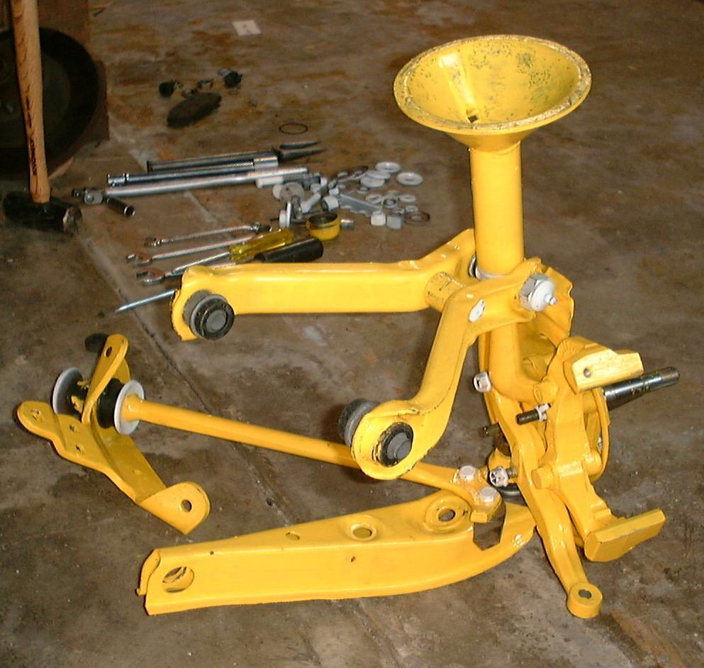
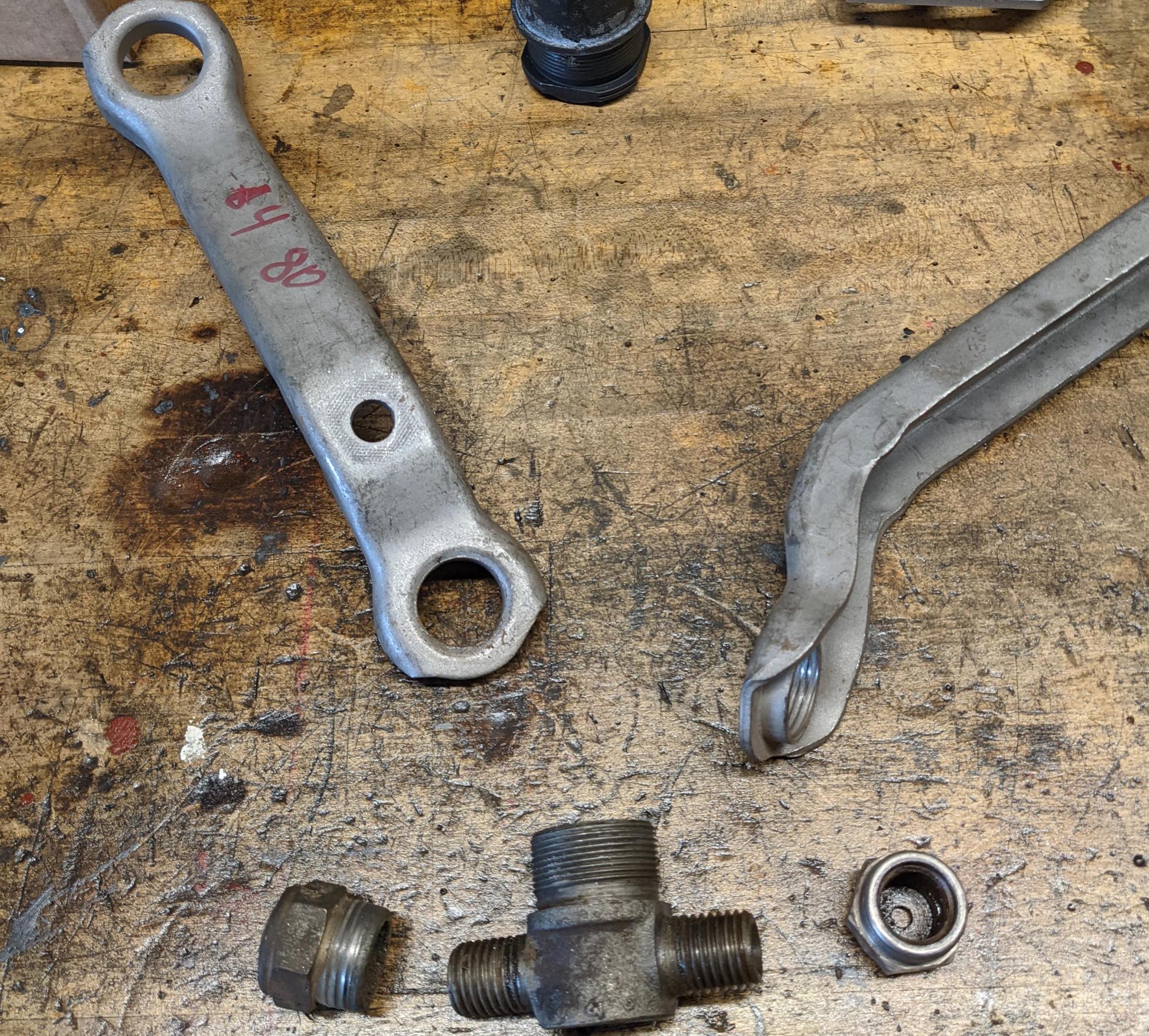
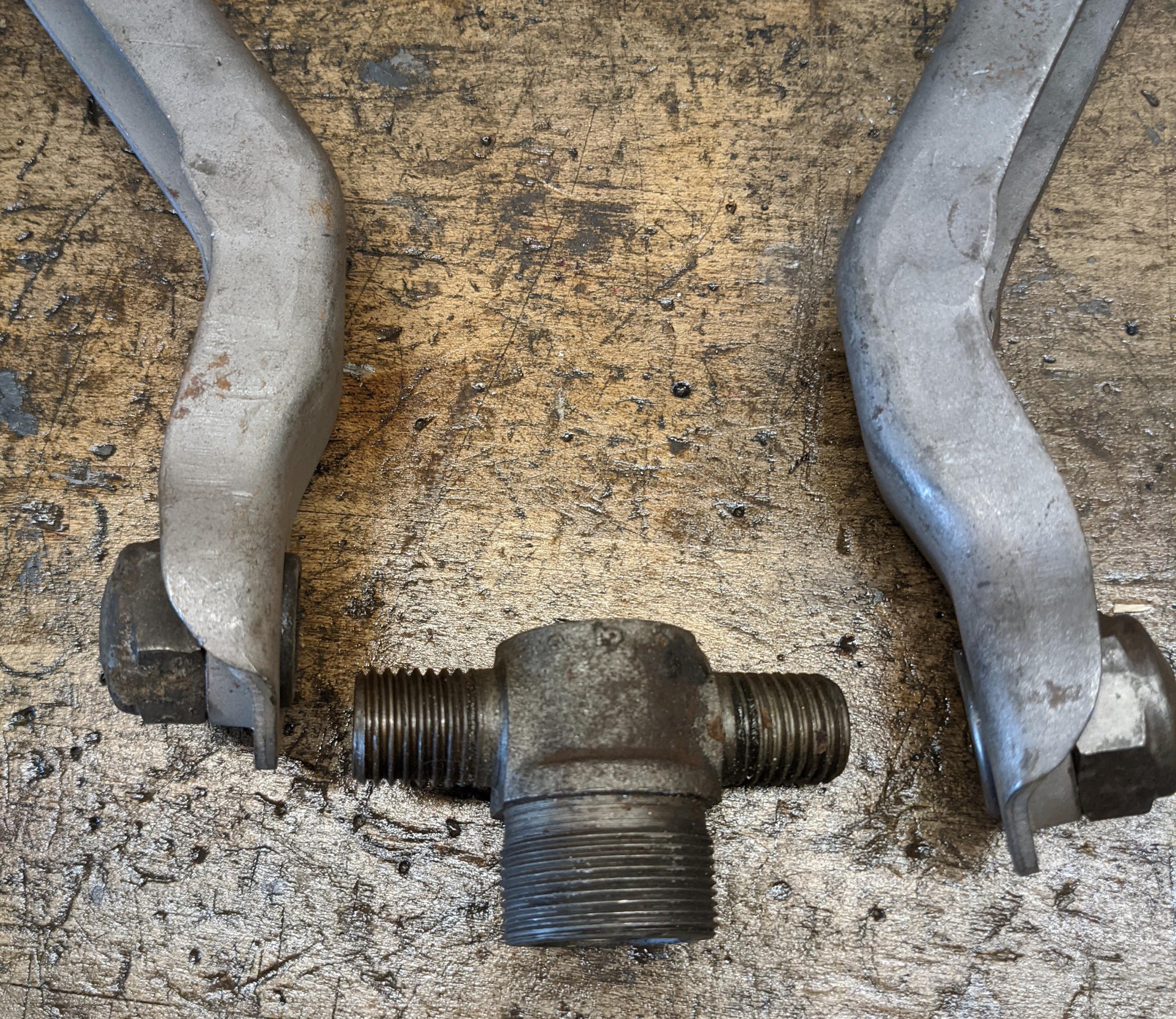
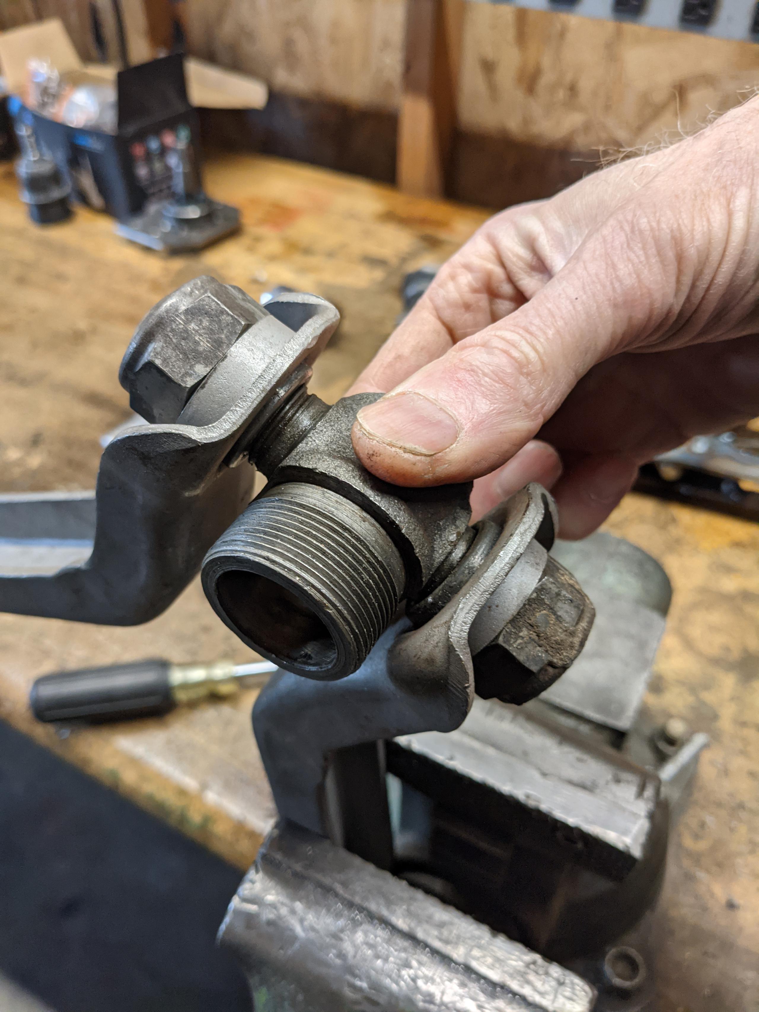
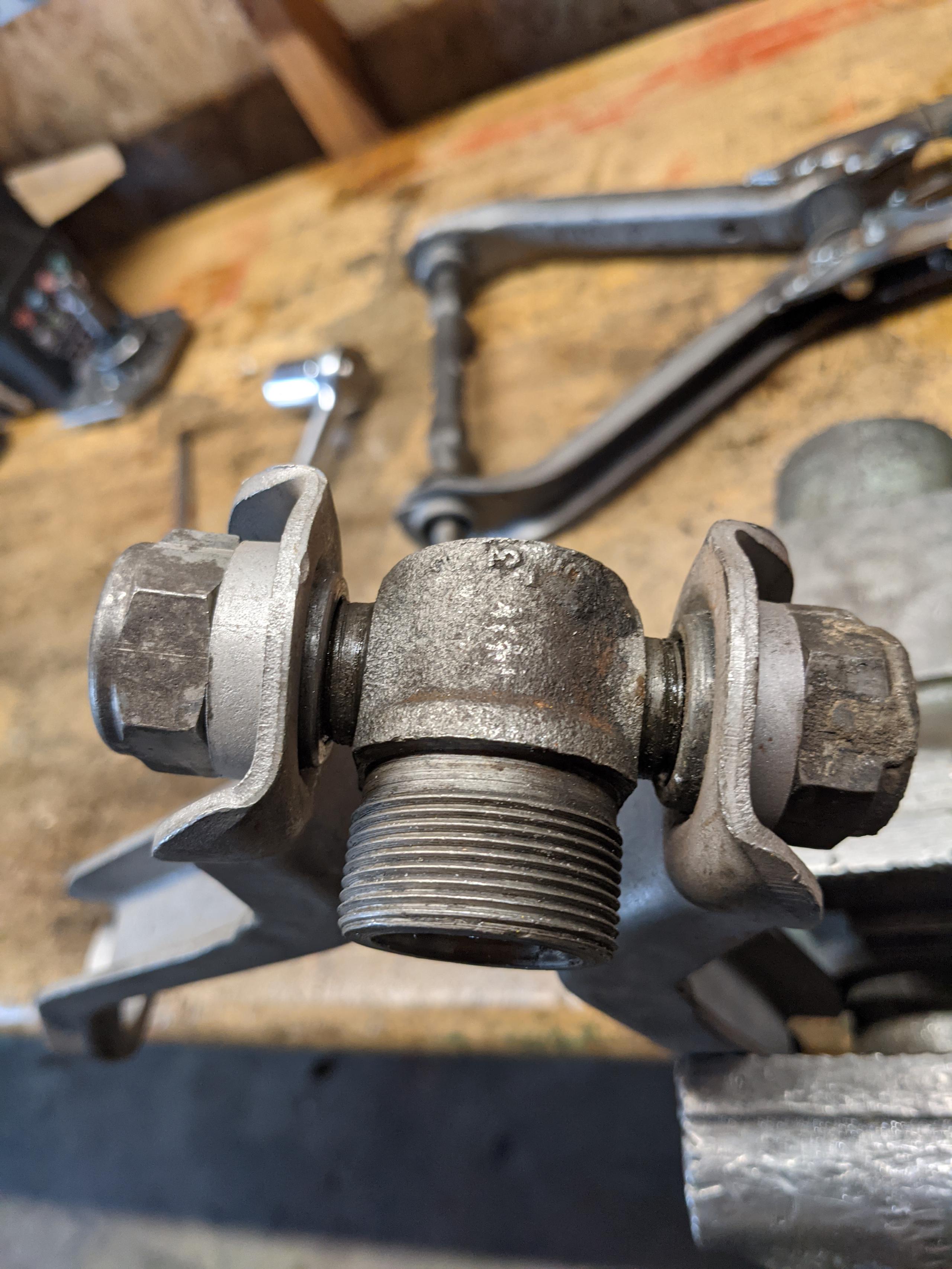
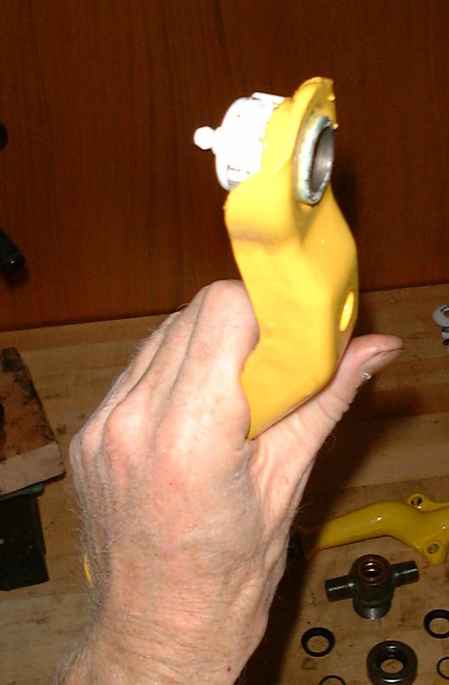
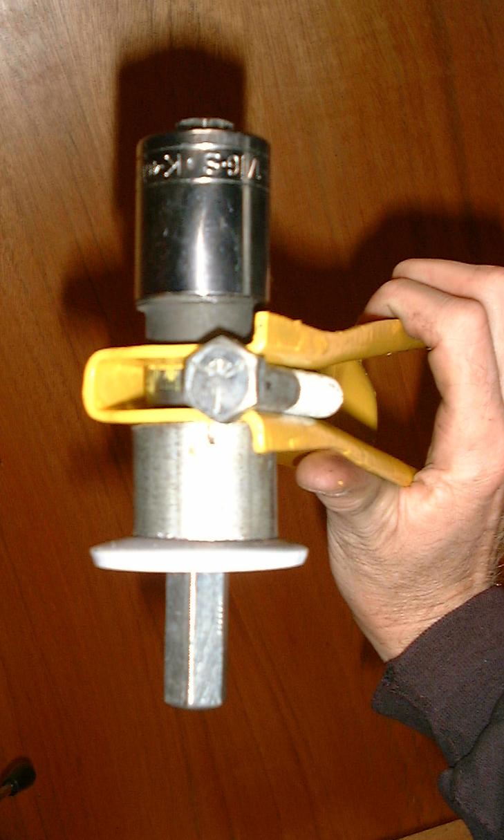
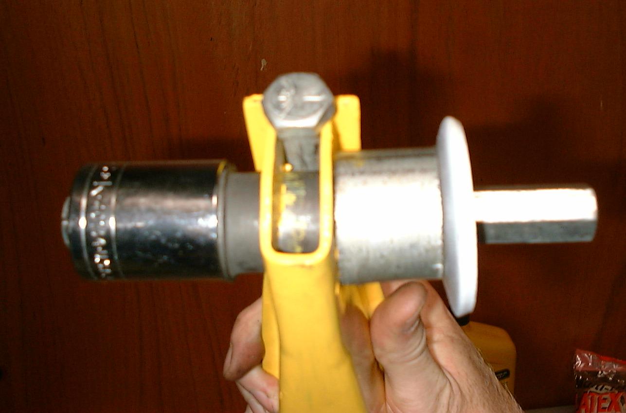
BEGIN: These are the basic components of the upper control arm trunnion
system. The bushings should be installed first (not installed here).
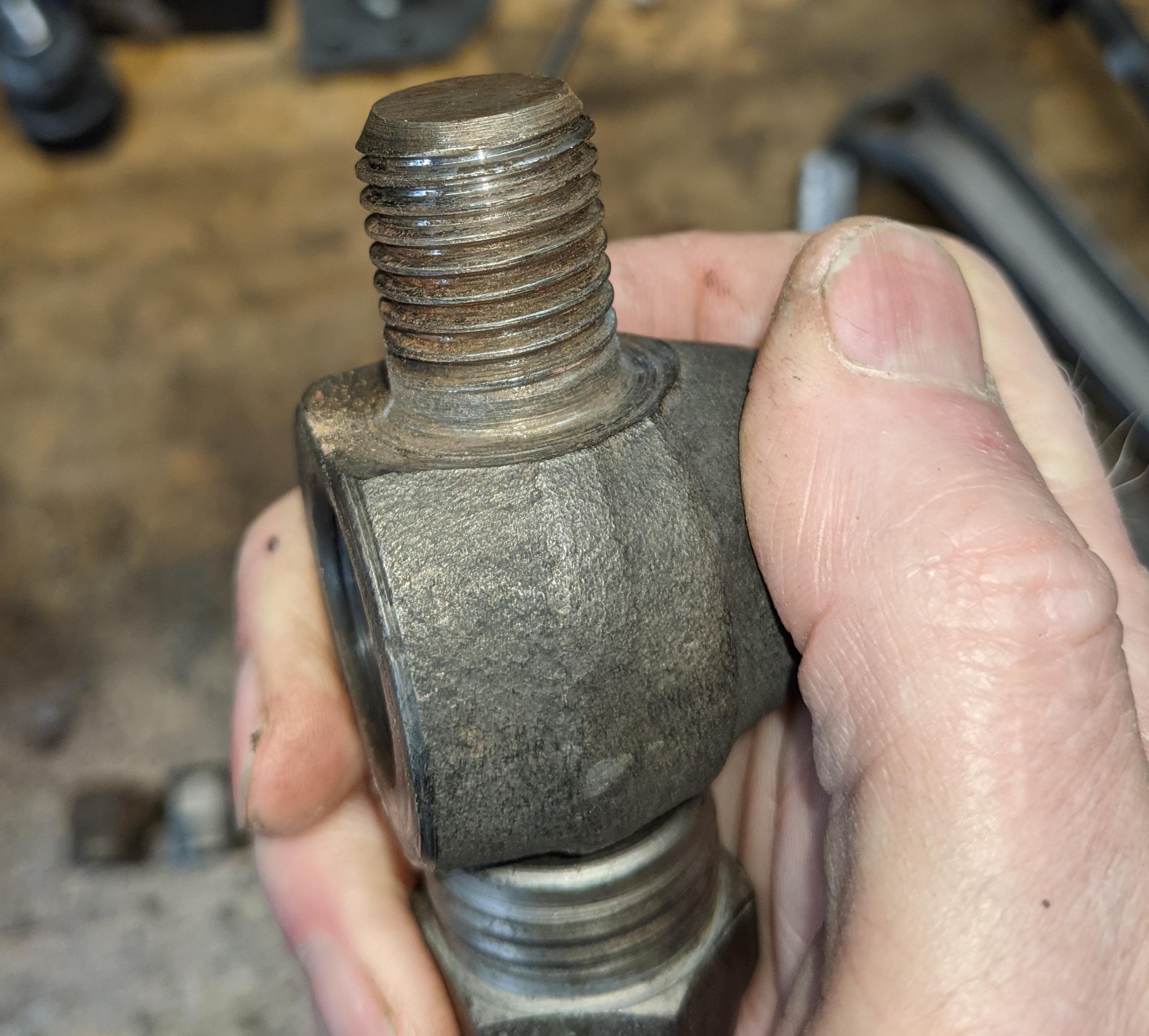
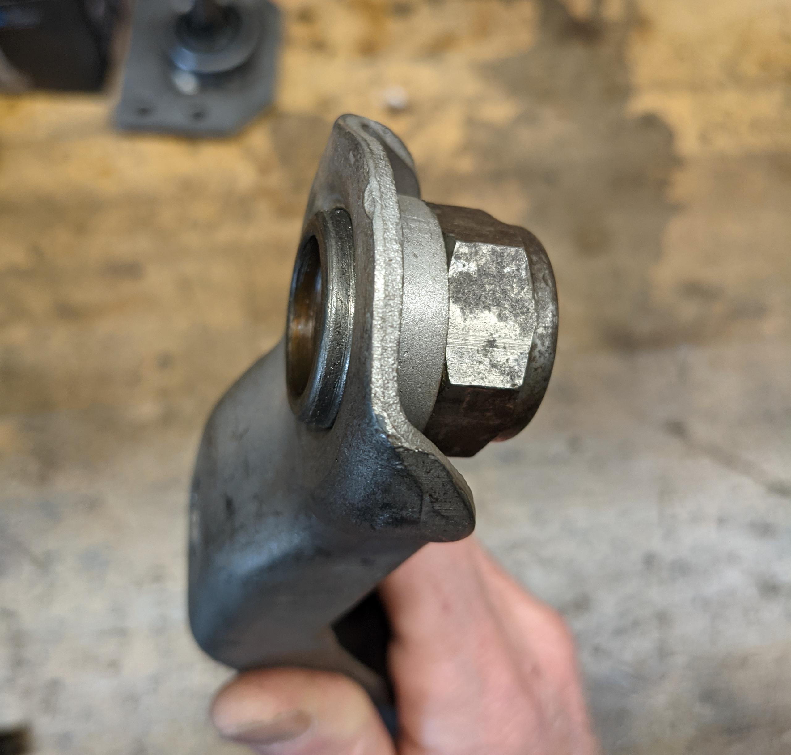
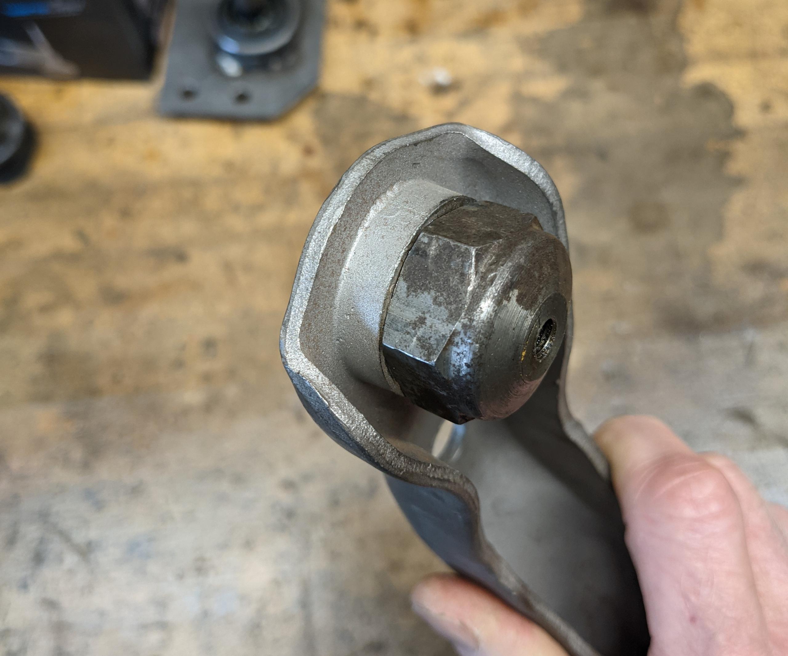
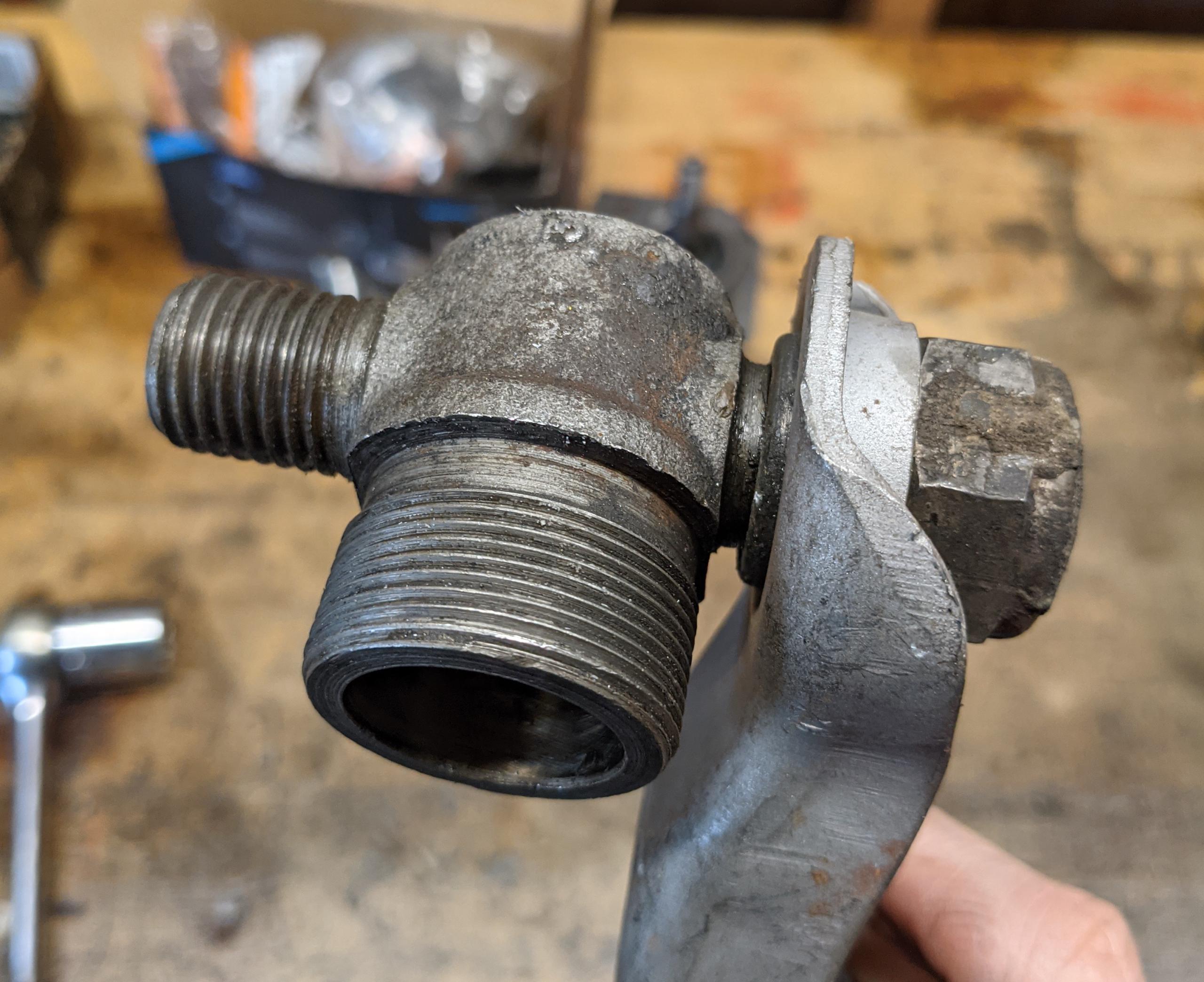
STEP 1: Thread each trunnion cap into each arm, and torque to XX ft/lbs.
This will be the final assembly and torquing of the trunnion caps. Note that
the underside of the cap “head” is cleanly flush with the arm metal — no gap.
If it is not square, the arm shallow threads are stripped and the arm must be
replaced. It is all too easy to cross-thread the nut into the arm. Go slow,
hold it square to the arm, and try to install by hand. If tools are required to
start it, be extra careful.
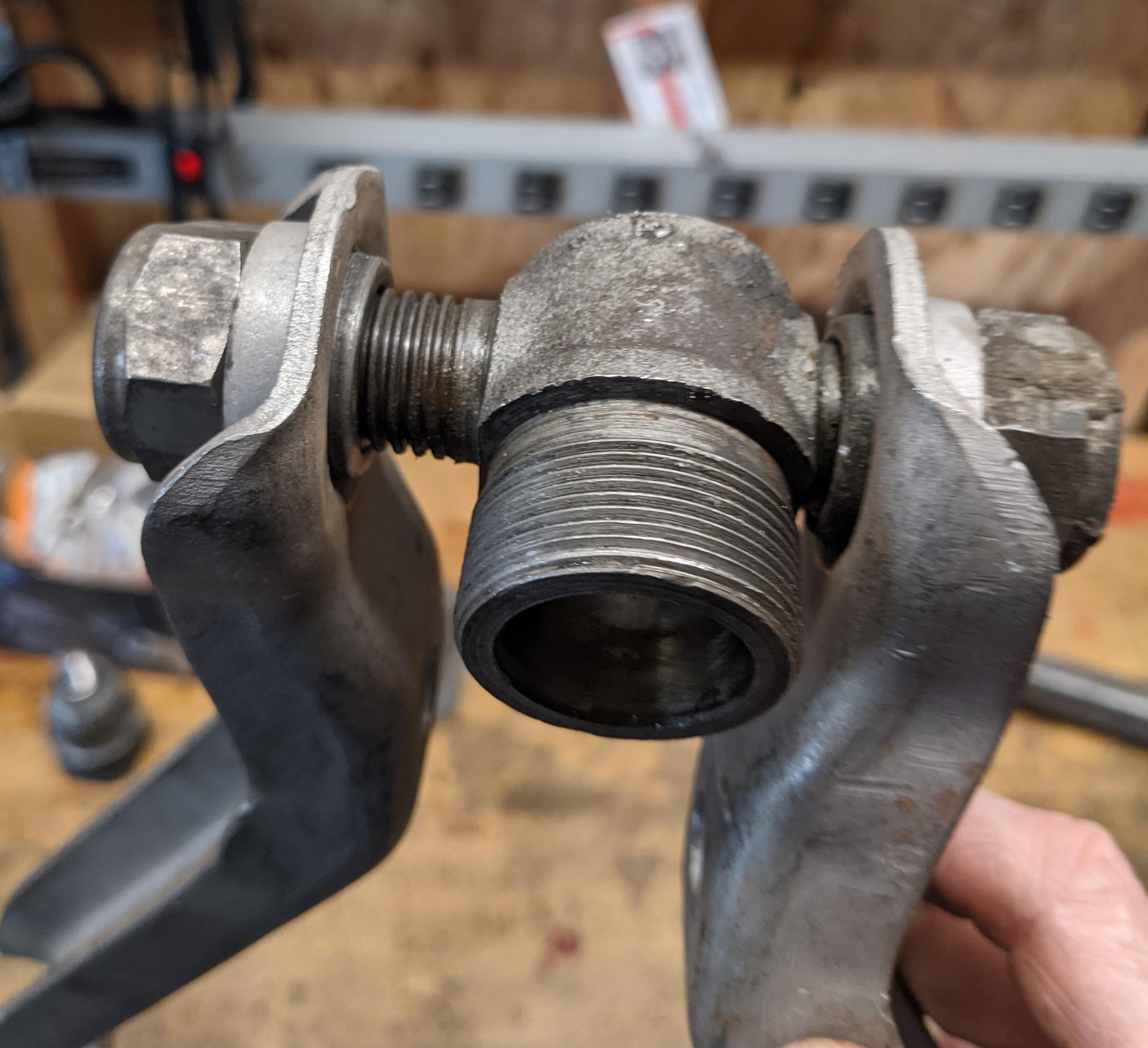
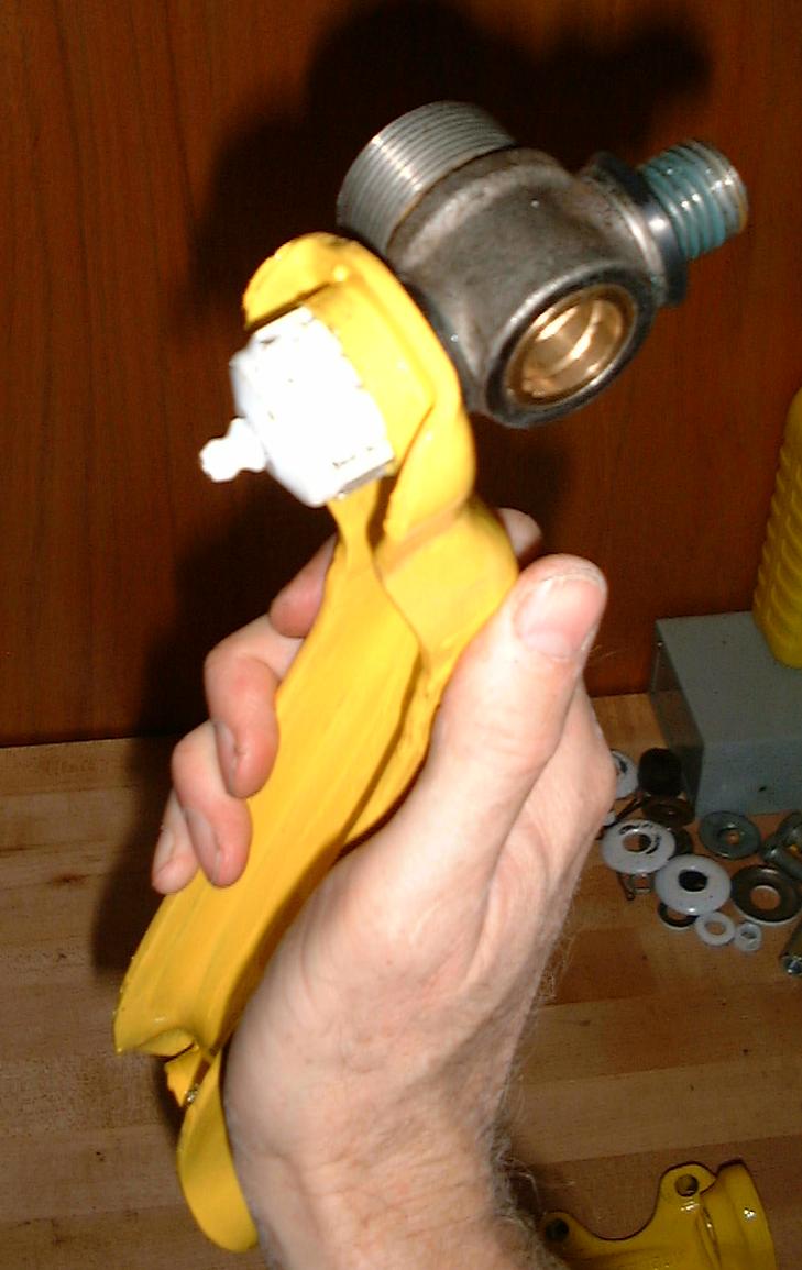
STEP 2: Now ready to assemble the two arm-plus-caps and center trunnion casting
into the control arm. This trunnion is too dirty to use in a car, for the record.
Do What I Say Not What I Do Department: Install grease seals onto the
trunnion arms before assembly. Grease seals, fat O-rings are as good/better than
the factory seals, will not be shown in this sequence. I left them off here so
that you can see what is going on.
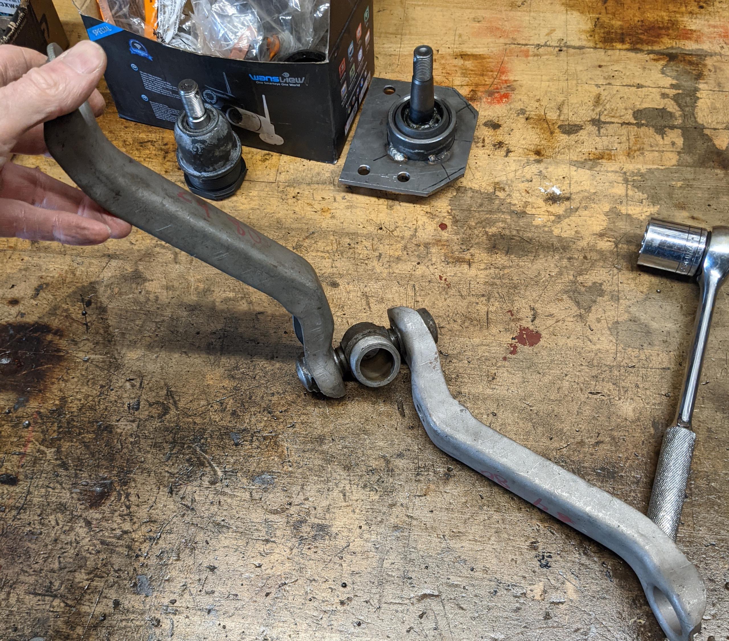
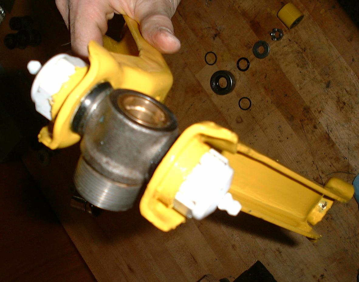
STEP 3: Install the trunnion casting into one arm (doesn’t matter, they are
identical) and just run it down. If the inside of the cap is not clean, it will
bind. Don’t “tighten” it, just take up all the slack.
STEP 4: Add the remaining arm half to the trunnion. Thread it on a couple of turns.
STEP 5: This would be best shown on a video, but I don’t feel like making
videos, and in 20 years this HTML will persist, whereas Youtube and TikTok, who
knows, so now’s a great time to practice visualization (lol). The two arm halfs
are free to rotate on the trunnion center portion, any part can move.
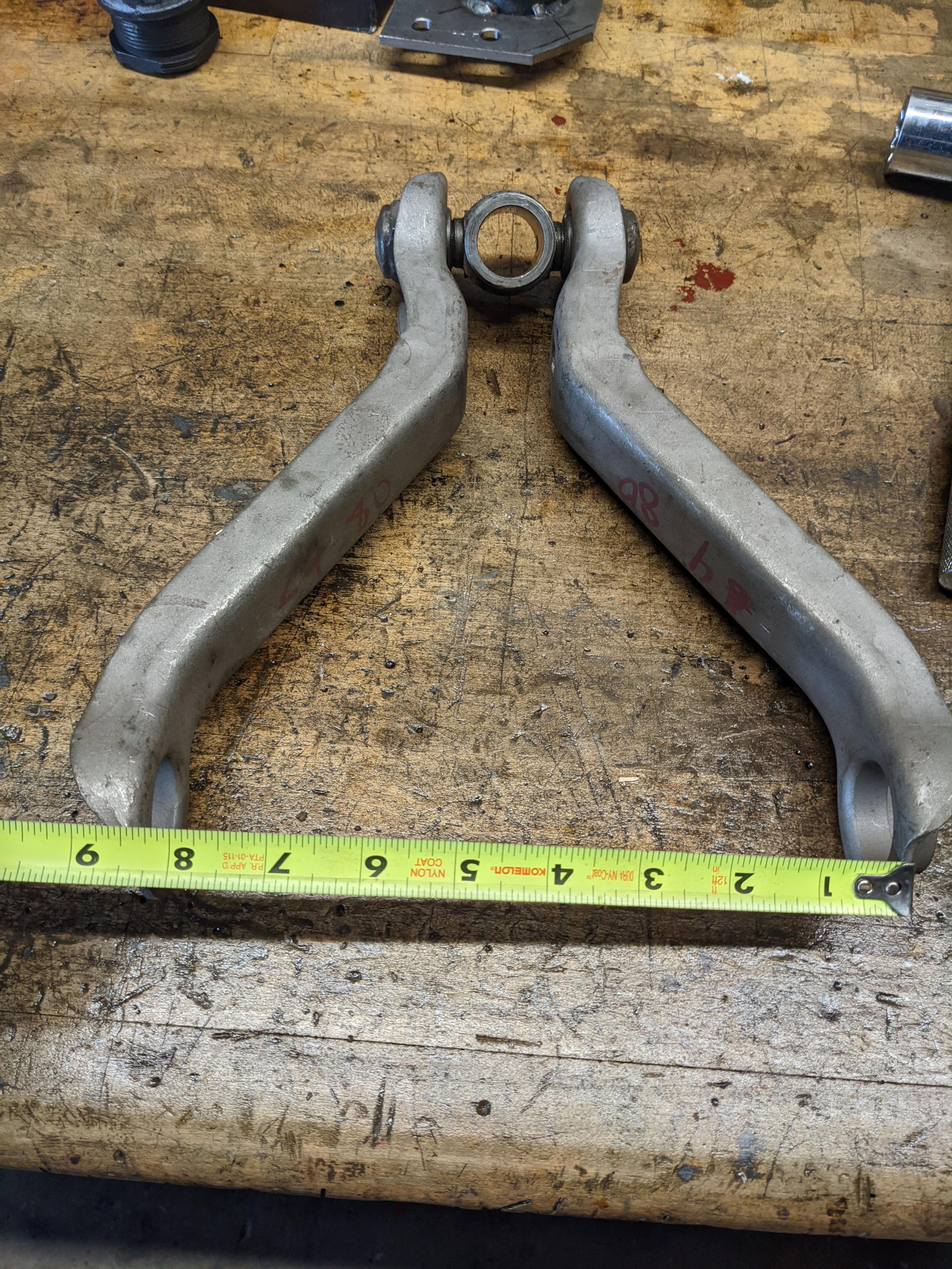
Rotate (thread) the most recently added arm further onto the
trunnion, and every full turn, flop it down onto the table and measure the
distance between the inner edges of the bushing ends of the arm.
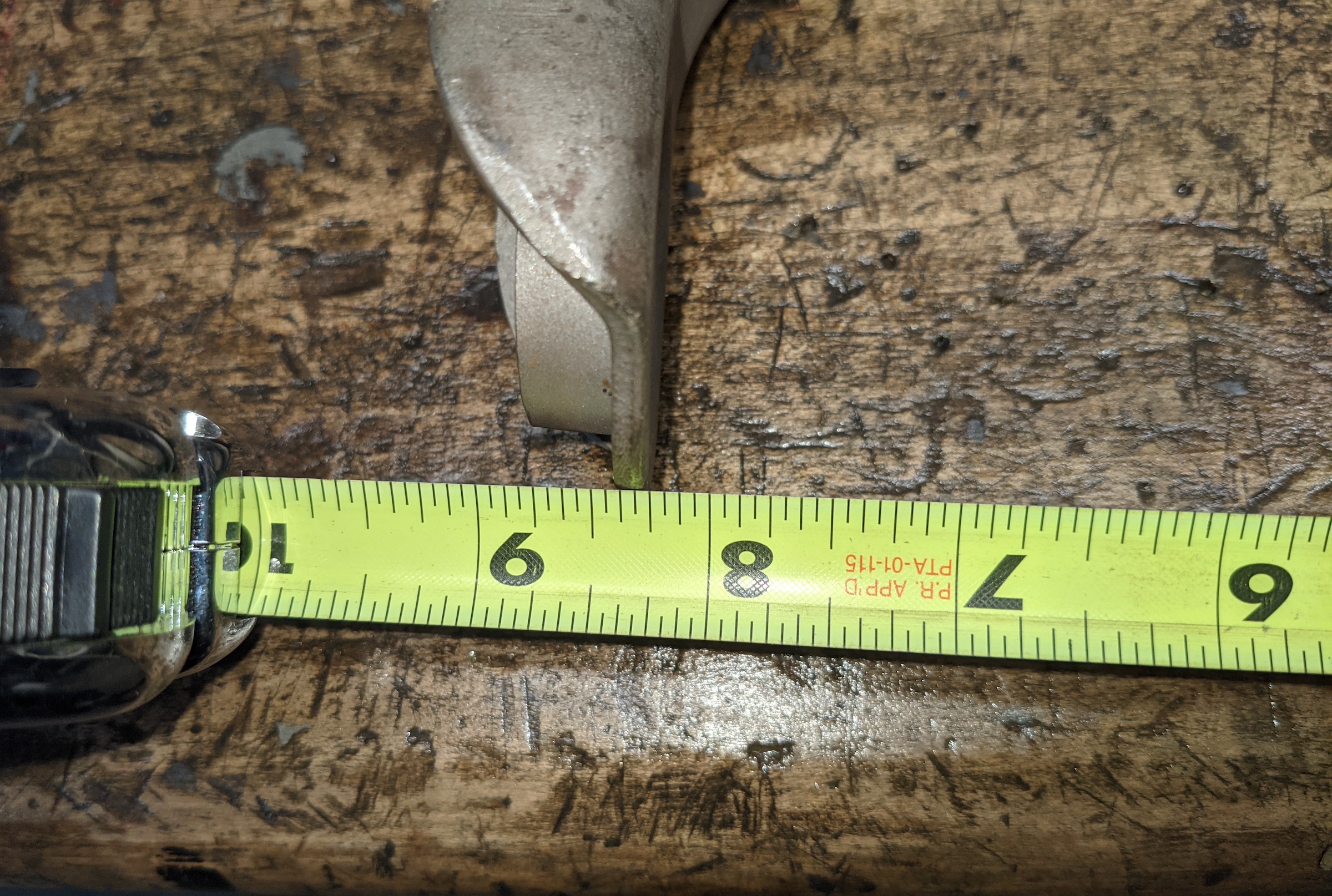
The only dimension to worry about at this step is that measurement between
the inner tips of the bushing ends of the arm. Each full turn is about 1/4″.
IF YOU CANNOT GET EXACTLY 8.25 INCHES: STOP. There is something wrong. Do
not proceed, and absolutely do not install this on a car, it will
self-disassemble. Parts may be bent, the caps not seated squarely in the arms,
etc.
Insert the spacer/stiffener between the flats on the small end of the arm
and torque to XX ft/lbs (not shown here).
If you get 8.25″ between the arm tips, and with the spacer/stiffener
installed and torqued the trunnion will not turn freely in it’s space between
the arms, Something Is Wrong. It may be that the arm ends are bent, caps not
square in the arm ends, or the inside of the trunnion caps are dirty. This must
be fixed before this assembly can be used in the car.
STEP 6: Now go back and look at the trunnion end. The trunnion wants to be
centered, but is probably not. Simply rotate the trunnion center casting in half-turn
increments until it is close to exact, within 1/16″ of centered. (Any remaining error
will be adjusted out when you subsequently align the suspension.)
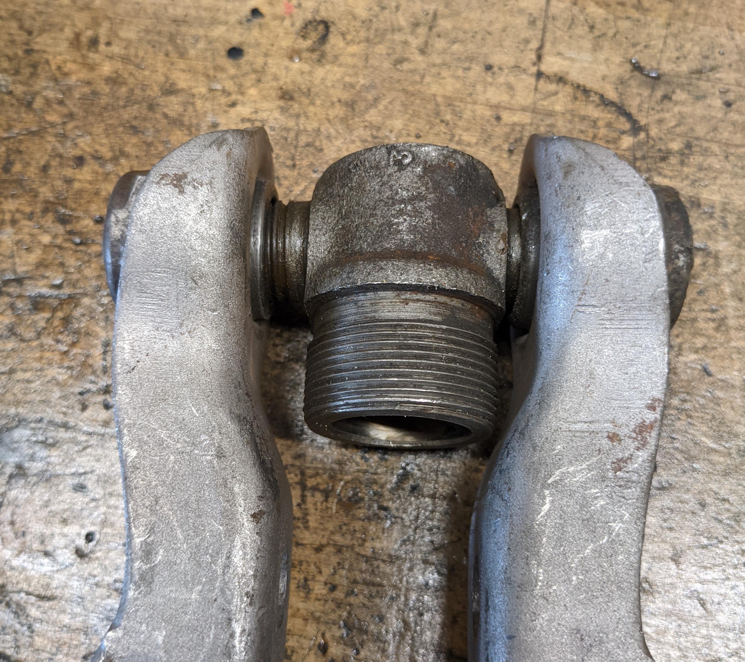
STEP 7: This is the trunnion, centered in the arm, of course sans seals for
the photo sequence.
Special note on upper A-arm bushing installation
This is another one of those things left out of the TSM.
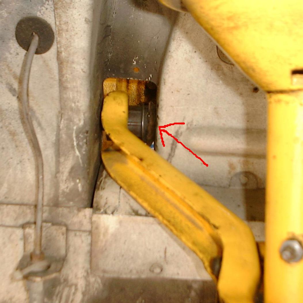
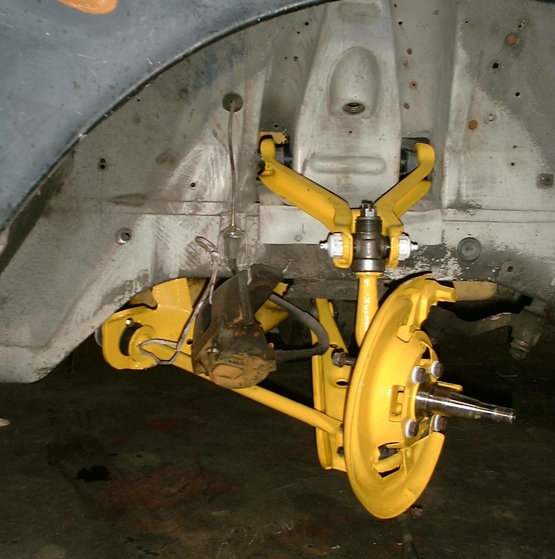
The upper A-arm pivot bushings, the ones that the caster and camber
adjusting eccentrics run through, should have a dished washer placed or crimped
over the inner sleeve, where it faces the chassis, on the inside of the upper
A-arm (see first photo).
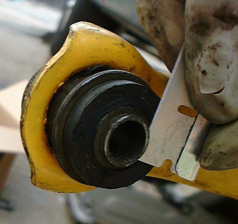
The problem is that most replacement press-fit bushings are not exactly
correct; the rubber is brought out flush with the end of the inner sleeve.
Unfortunately on the early cars this doesn’t work right; the inner sleeve works
its way into the chassis pivot hole and eats away at the end of the sleeve and
elongates the hole. The solution is to cut away the rubber, as shown in the
photo, and install the dished washer as it should be. The washer not only
transmits the (small, but non-zero) side forces evenly, but the dished shape
helps installation.
Trunnion (component) reassembly, 2005 version
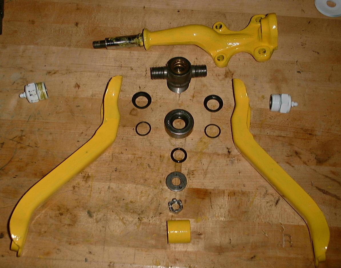
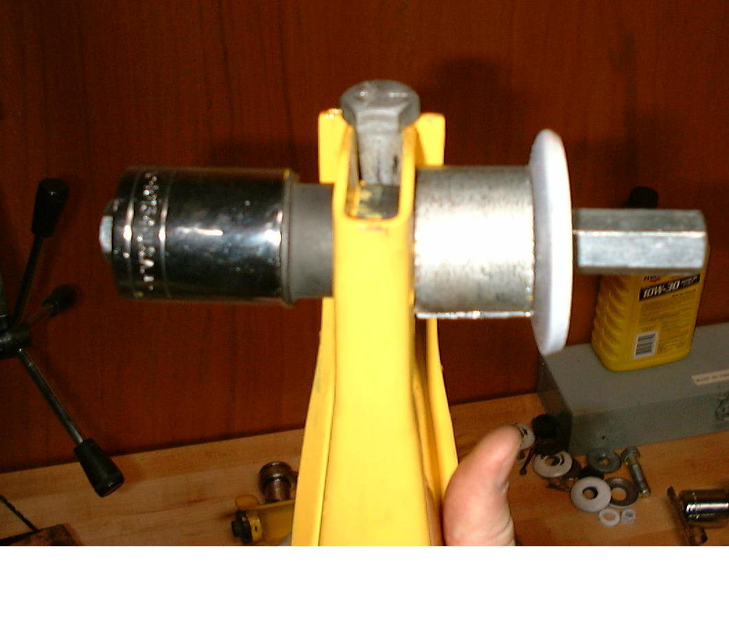
The trunnion consists of a cast steel center cross with bronze bushing, two
doubly-threaded cap nuts, a thrust bearing and assorted hardware; the steering
knuckle is shown at the top of the photo. If lubricated at all, there is very
little to wear out; recommended interval is 30,000 miles, and you need to
remove the vent plug to grease it (RTFM).
The thrust bearing carries the downward suspension force and eventually
wears, reasonably gently, and in a fail-safe manner. In 2020/2021 the part is
readily available, Nice (brand) bearing 608V, available on Amazon, even. There
were two outer-diameter bearings used in trunnion suspensions; the smaller
diameter used on the early (63-64) cars are made of unobtanium, but allegedly
you can simply install the larger one and let the dust-cap ding on the A-arm,
the race is supposedly the correct size and only the dust cover is larger. I
haven’t tried this, but eventually I’ll have to. My thrust bearings were still
good at 190,000 miles (take that! late-model cars). They were in good shape
when I disassembled for initial inspection when I first got the car, at 87,000
miles.
When you first look at the trunnion system, you may find the design to be
somewhat baffling (I did). That’s because there’s actual subtlety in the
design. It’s rather clever in fact.
A trunnion is essentially a U-joint, and works the same as one in a drive
shaft. The steering knuckle runs through the bronze bush, vertically, and
allows the wheels to turn. That part is as simple as it appears to be.
It’s the upper “A” arm assembly with the two doubly-threaded caps that is a
bit of a puzzle, at first. The caps thread into each A-arm half with a weird
shallow thread and simultaneously threads onto the trunnion itself. If
all five parts (two arm halves, two caps, one trunnion) are not threaded
together exactly correctly you’ll stress the hell out of the parts and
ruin them driving. The width of the wide end of the A-arm assembly (that fits
into the chassis) depends on correct trunnion assembly too, and will ruin the
press-fit rubber bushings if they rub on the chassis. The TSM is utterly silent
on these little details.
(One of the subtleties is the weird double-threading. It’s for safety,
basically. The upper A-arm is held together not only by the obvious grade 8
bolt and spacer, but by the five threaded trunnion components. The trunnion
would work just fine, in the normal case, if the caps simply threaded into each
A-arm half and the trunnion had plain bearings, but would catastrophically
disassemble should upper or lower arm components fail, such as in an accident
(or worse, be pre-stressed into later unexpected failure by a an earlier
survived accident). As the suspension moves up and down, the steering knuckle
moves fore and aft, due to the threads. It’s just a small amount, but normal.
Good engineers design for the worst case, not the best case!)
Special note on upper A-arm bushing installation
This is another one of those things left out of the TSM.
The upper A-arm pivot bushings, the ones that the caster and camber
adjusting eccentrics run through, should have a dished washer placed or crimped
over the inner sleeve, where it faces the chassis, on the inside of the upper
A-arm (see first photo).
The problem is that most replacement press-fit bushings are not exactly
correct; the rubber is brought out flush with the end of the inner sleeve.
Unfortunately on the early cars this doesn’t work right; the inner sleeve works
its way into the chassis pivot hole and eats away at the end of the sleeve and
elongates the hole. The solution is to cut away the rubber, as shown in the
photo, and install the dished washer as it should be. The washer not only
transmits the (small, but non-zero) side forces evenly, but the dished shape
helps installation.
Upper A-arm assembly (original 2005 photos and description)
This is the original 2005 version. It was lacking clarity on some details
hopefully fixed above, but I keep it here for completeness.
Thread a cap into each A-arm half. Tighten by hand at this point just to
take up slack.
Install the grease seal onto the threaded trunnion arms (wide end out) and
thread the trunnion onto one of the arms. Just run it down, do not tighten.
now do the same with the other arm. it now begins to look like an A-arm.
![]()
the following steps take advantage of the fact that the trunnion threads
into the caps. NOTE: this pic shows the arm assembled, with spacer and bolt
tightened. the bolt isn’t inserted until these steps are complete. i didn’t
take enough pictures, sorry. what i wanted to show is essentially the previous
image but held as shown here.
STEP 1: place the A-arm on a flat table and set the spacer in place. it
probably won’t fit right the first try, likely too loose (a gap) or too tight
(requires force, pushes the arms apart).
STEP 2: to adjust, hold one arm-half in one hand, rotate the other arm-half;
counter-clockwise to increase the spacer’s gap, or clockwise to close the gap.
at this step, do not worry if the trunnion isn’t centered between the arm ends.
that’s done later.
repeat until the spacer fits snugly but without any force or gap. when you
have it correct, insert the bolt through the arms and spacer and tighten it. if
you have it correct, with the spacer-bolt tight, the trunnion will turn freely
in it’s place between the arms. if it binds, you have it wrong, remove the bolt
and repeat the three steps.
As a further check, measure the distance between the outer, wide part of the
A-arm assembly. It should be 8.25″ inside to inside. With the upper arm
bushings pressed in, the A-arm assembly should *just fit* into the chassis. If
you’ve assembled the trunnion wrong, it will either scrape on the inside of the
chassis (trunnion caps too far apart) or jam onto the chassis inwards (trunnion
caps too far apart). If you’ve got the spacing correct, the trunnion will
pivot freely and the A-arm will fit nicely into place in the chassis. If it
doesn’t just fall into place it’s not right!
![]()
at this point the A-arm looks like an A-arm; however the trunnion itself is
probably not centered, closer to one arm or the other. now we fix that, again
taking advantage of the threadded trunnion. the A-arm assembly is symmetrical;
there isn’t a top and bottom or left and right. simply turn the trunnion 180
degrees and check again. when centered, the side with the threads for the
spring perch is “up”. done!
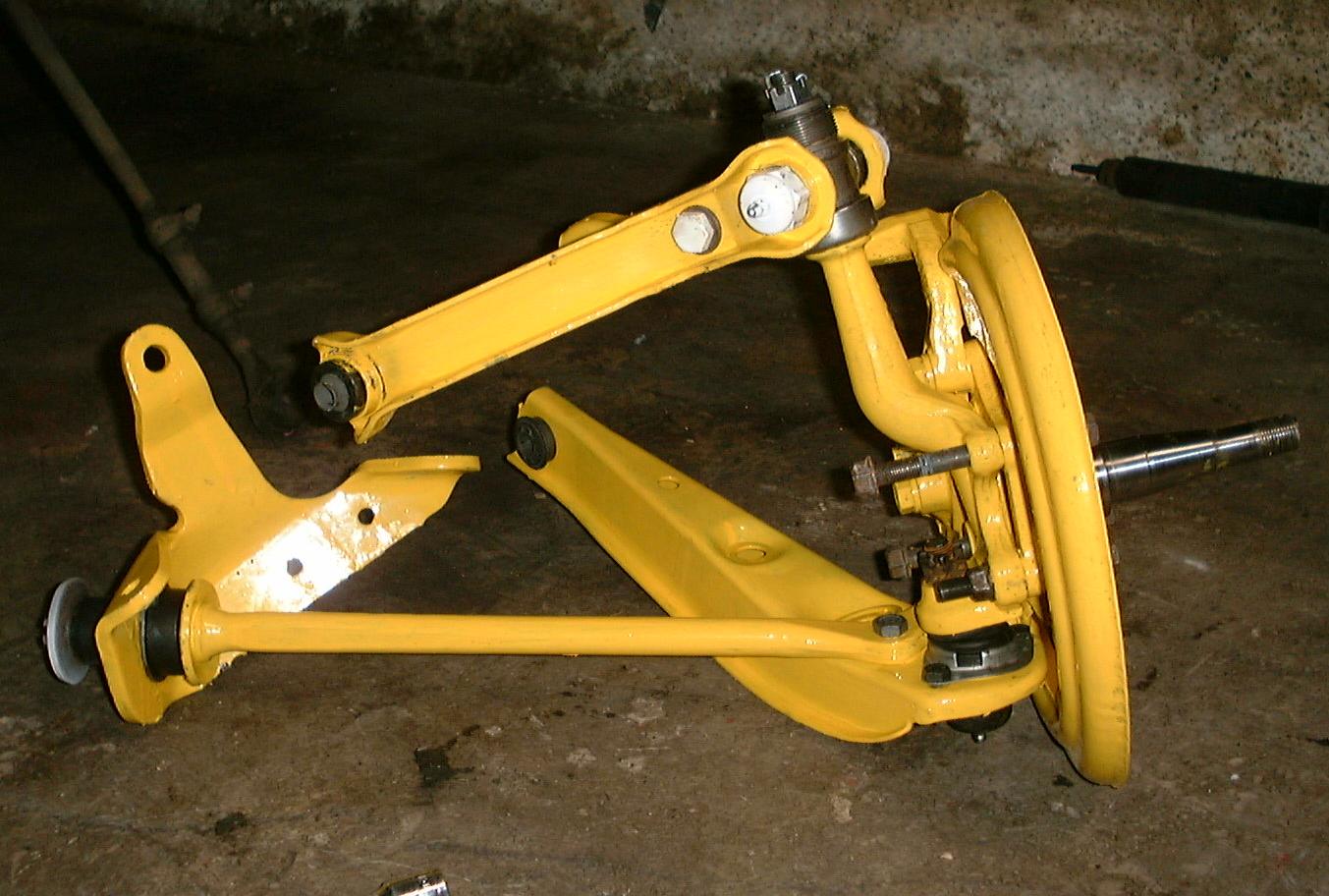
Once you’ve got the A-arm assembled right, the rest is easy. The steering
knuckle simply runs vertically through the thrust bearing and trunnion; don’t
forget the O-ring grease seals. The castellated nut (with washer) on top should
just be run down with your fingers; there’s no need for preload here at all. I
finger assemble and move to the nearest hole for the fattest cotter pin I can
find (a steel pin would be better). You can see the nut and pin in the image to
the right, where it lives under the spring perch, not yet installed.
extra pictures
Deprecated: File Theme without comments.php is deprecated since version 3.0.0 with no alternative available. Please include a comments.php template in your theme. in /home3/amcmagc1/public_html/wp-includes/functions.php on line 6114
Leave a Reply