Cylinder Head
10-29-2025
This section covers the head, head bolts/studs, intake trough, valves, rockers, exhaust ports and mods, and pistons. head oiling, camshaft and especially lifters, valve springs and related are mentioned. It is mainly information from Tom Jennings, with editing by Frank Swygert.
Overview
The head design on the 195.6 seems unusual, but it’s really not. Nash has used a similar design since at least 1940. The lower part of the intake was incorporated into the head with an aluminum top cover with the carburetor mount built in. This design allowed for faster warm ups and better fuel vaporization. Flow is actually better than you’d think with the short “runners” between the intake channel and the valves. The only drawback is this design makes for a rather heavy head — it’s quite a big chunk of cast iron! Cast iron intakes were common until the 80s on most cars, mainly for the same reason — they retained heat and vaporized fuel better after they warmed up. Being able to take 10-15 pounds of iron intake off the head before removing it does help though! The big Nash sixes used this design all the way through the last one made in 1956.
Cylinder Head Cooling
There is a serious engineering flaw in the cylinder head design that is a major source of failure and other problems with this engine. As serious as it is, there are two fixes, one easily doable in your driveway. Please refer to the COOLING SECTION for details.
Re-Torquing
The factory technical service manual for these engines has the peculiar requirement of checking cylinder head bolt torque every 4000 miles, and re-torque every 8000, done while the engine is hot. This is just plain weird, and I am convinced this was due to the head expansion/thermal cycling of the head. In 1965 the cooling system was modified to solve this, the fix is easy to apply to earlier heads when the head is off. See the COOLING SECTION for details. With cooling system mods the re-torque seems to no longer be required; my annual check now consists of setting the torque wrench to 60 ft/lbs and simply checking for loose fasteners. Not even one fastener in an improved engine has budged in over 10 years. I consider the problem identified and solved, but since valve adjustment needs to be looked at every other year/8-10K miles, I check torque then anyway. It’s cheap insurance. The first sign of a loose head is an overheating engine, and this leads to warping and usually cracking of the head at this point — it’s likely been run hot several times over the last 50+ year. Old iron that has been overheated several times can be brittle and cracks easily. It’s very hard to find good replacement heads now.
Trough Intake
The head has a trough intake, adequate with short short paths to each cylinder, with one 90 degree turn each from carb to valve. Combustion chamber is a popup wedge. The trough has clever Nash anti-reversion wedges that make for excellent fuel distribution, at least.
Some of the intake ports are paired/siamesed, some are not. Front to rear, the intake pattern is I-II-II-I (II ports are siamesed). Fuel mixture is evenly distributed to the end cylinders, often a problem on inline sixes. Between cylinders 2 and 3 (and 4 and 5), adjacent to the second head stud from the front of the engine, you will see within the right hand trough wall a ramp-shaped protrusion cast into the trough. It pinches mixture flow at that point — it is a clever anti-reversion device, preventing back-flow of intake mixture pulses. All six plugs burn to the exact same color.
The trough is covered with a cast aluminum plate, a very handy design for hacking induction. It’s flat, easy to fabricate from scratch.
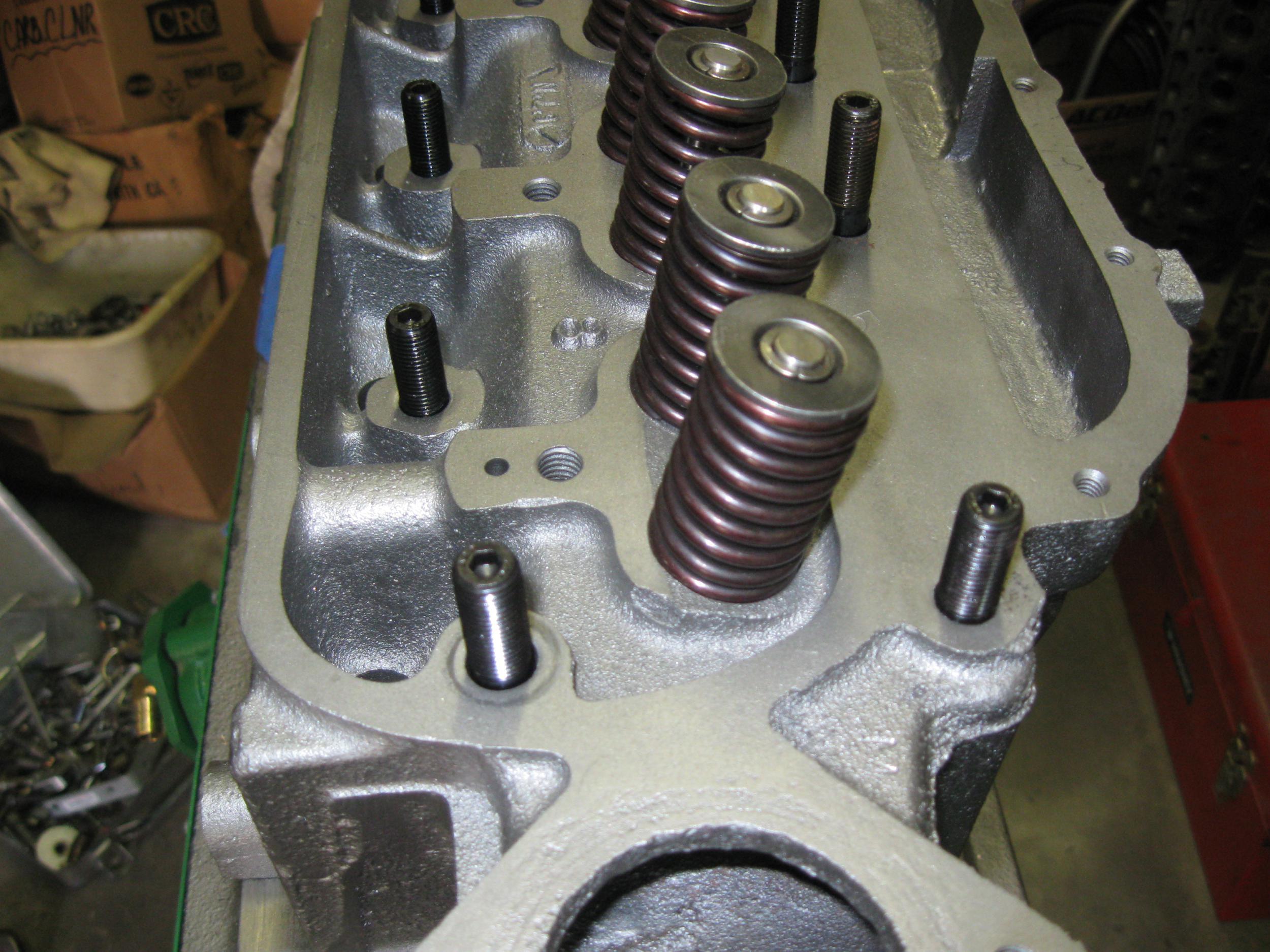
Valves
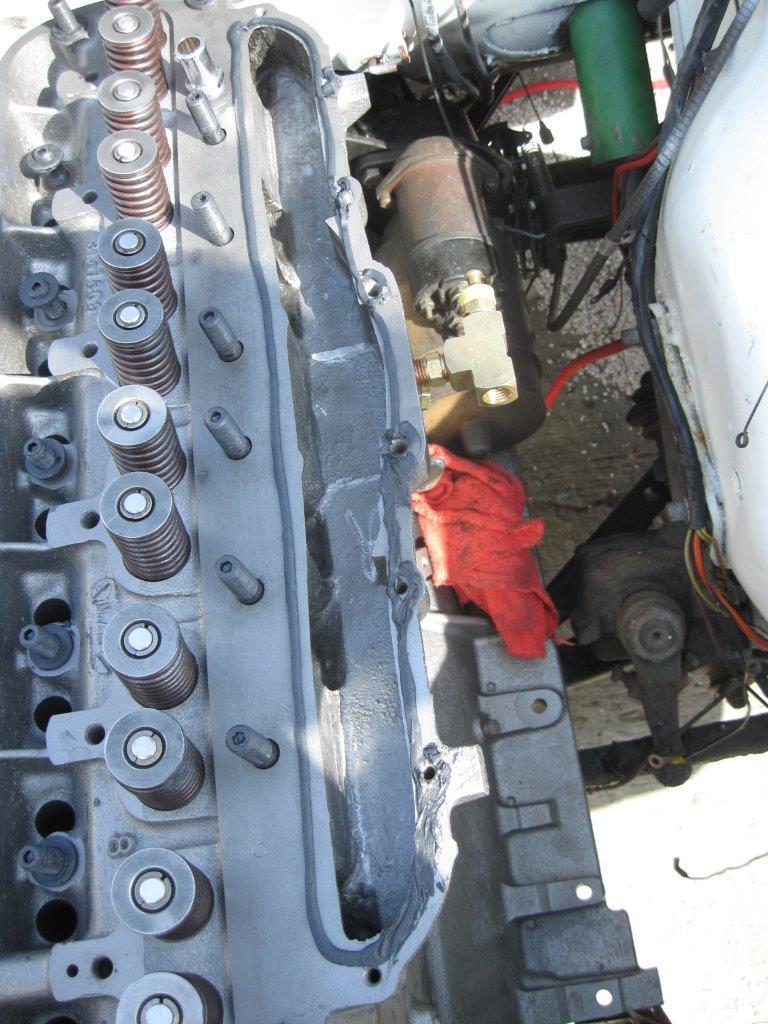
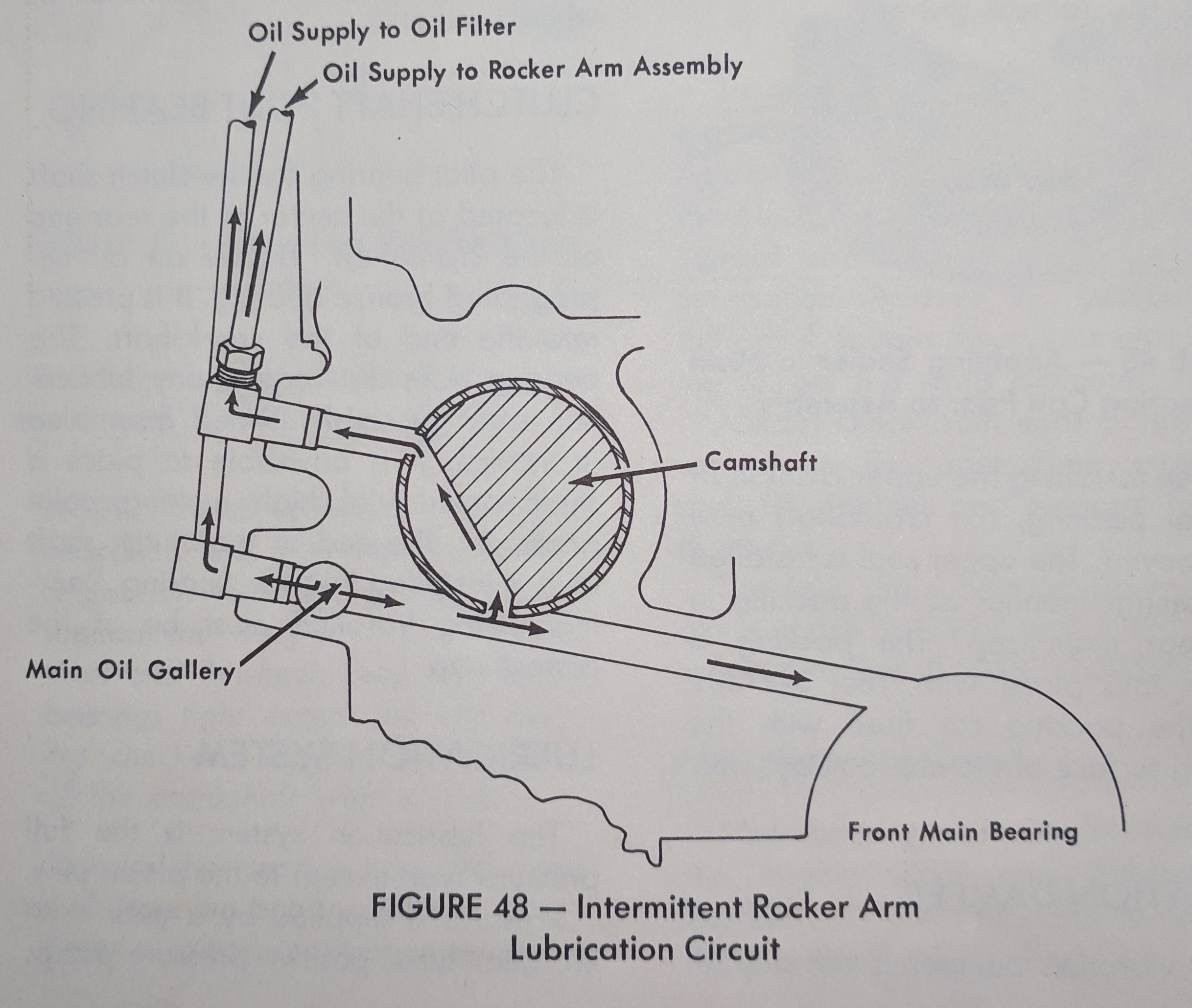
The valve setup is common enough — valves in the head with umbrella seals, springs and retainers, and serrated keepers (3-groove intake, 2-groove exhaust). Valves are operated by pushrods and adjustable rockers on a rocker shaft. Lubrication is handled by a pressurized rocker shaft, fed through the rocker stands from the head. The head casting is fed pressurized oil by an external line from the main oil gallery on the right side of the engine. This runs up to a 90 degree fitting in the side of the head. From there it goes through a drilled passage to the second rocker shaft stand and up to the shaft. When equipped with an oil filter a T was used instead of a 90 to pass oil through to the filter as well as into the head. Starting in 1963 this was changed. The oil filter got a separate feed from the main oil gallery. The head oil line came from the side of the block at the first cam bearing journal. The cam had a slot cut about 1/3 of the diameter that fed the head oiling line only when this 1/3 area was aligned with the hole in the block. This cut down the amount of oil pumped up into the head. It was necessary due to the engine being run more at prolonged highway speeds, where oil is pumped into the head faster than it can drain back. Prior to 1960 or so there were few roads where sustained cruising speeds could be maintained. By the early 60s there was enough of the Eisenhower Interstate System consrtucted (and under construction) that it had become a problem for the old design. This was a patch to get a few more years out of the engine, until the new clean sheet design 232 could be introduced (late 1964).
Valve springs should always be measured for height and tension, especially for this engine . The OHV and flat-head versions have identical-looking springs, but OHV springs are 80 pounds of force at the seat and the flat-head engine only 40. In 2010 I (Tom) purchased new supposedly OHV springs from Kanter and found that they were all 40 lb flat-head springs.
Rocker Shaft Assembly
The rocker shaft assembly is straightforward and reliable. The shafts wear and new ones are in short supply (AMC Acres and maybe other vendors have a few NOS shafts). I’ve had no trouble with the rockers nor the adjusters. New adjusters are available.
The rocker shaft can’t be inverted to wear the other side, as oil ports are milled into it to lubricate the bottom (loaded side) of the rocker. A shaft could easily be made by a machine shop, but it needs to be hardened tubing. Plain steel would wear much faster.
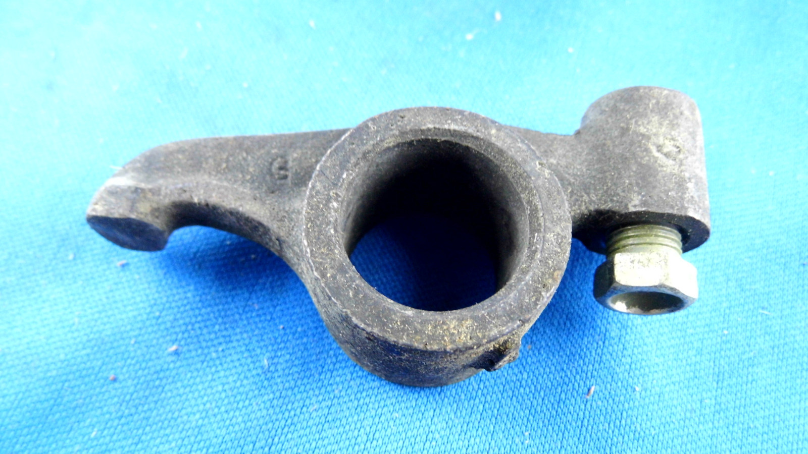
A single rocker pictured below. The adjusting nut is clearly visible to the right. A 7/16″ wrench is used to turn the nut, which has a spherical recess to hold the pushrod in place.
Improvements
Head Studs, Not Bolts
Most of the following are improvements to the cylinder head or it’s attachment and sealing, useful only when the head is off and apart. Even if you are doing a freshen-up on a dead-stock motor you should consider some of these improvements.
In 2010 I (Tom) replaced all of the old head bolts with studs, nuts and washers designed for this job, from ARP (Automotive Racing Products). These are superior to bolts, relatively inexpensive, and so easy to do that I recommend this for even the plainest stock engine. As long as you remember to torque the head bolts every 8-10K miles (when valves are adjusted) or every three years this isn’t really necessary, but it may save a head for a later owner who doesn’t know to do this or neglects to. Valves out of adjustment will cause a loss of power (loose valves) and maybe a bent pushrod if one comes out, but won’t damage the head beyond repair.
Head to block sealing is a very weak area of this engine. There is a single source for headgaskets, Best Gaskets (the 195.6 OHV gasket is part number 527G), of the old metal-sandwich construction. It needs a very flat surface and unlike modern gaskets, sealer. Tom has found through experience that Permatex Aviation Form-A-Gasket #3 works well, Frank typically uses Permatex Copper Spray-A-Gasket #80697 or Indian Head Shellac #20539 — all three work well, just DO NOT try to use something thick like RTV!
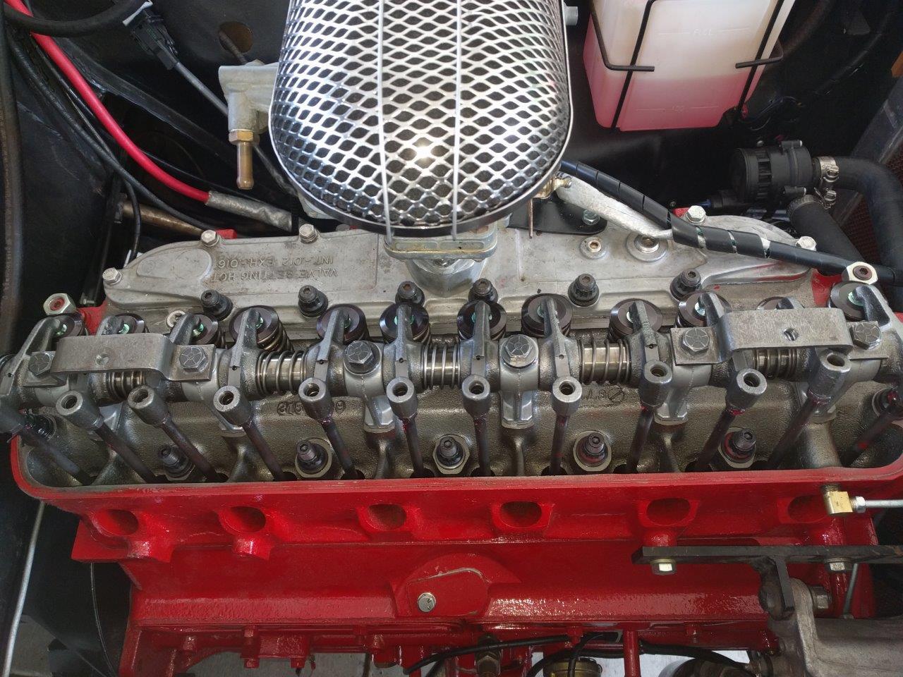
Here are some pics of the studs installed in the block and with the head on. This is Tom’s 2010 build.
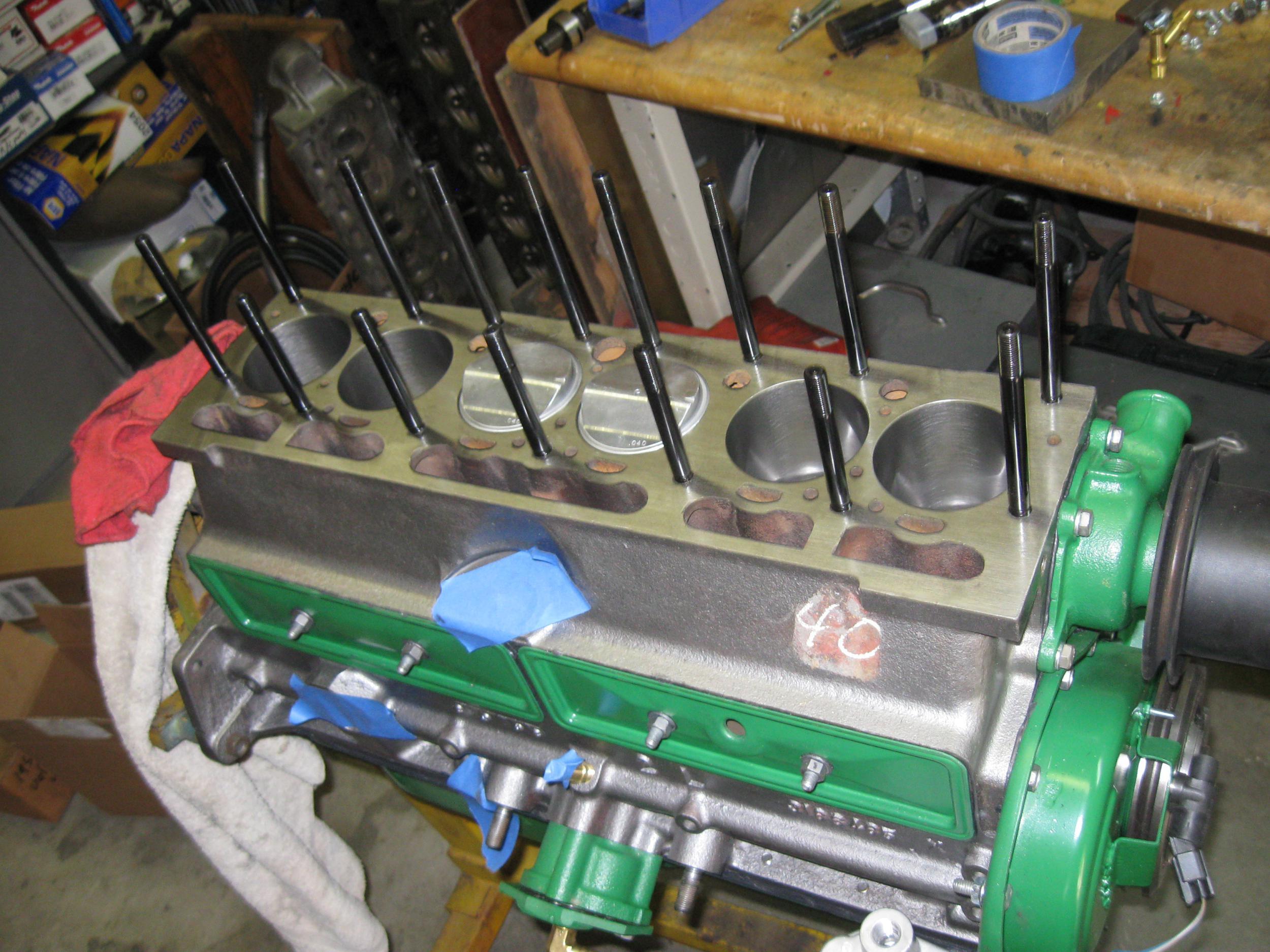
Studs are superior to bolts for this application. When a head bolt is torqued, it remains twisted along it’s length, due to friction in the threads and under the bolt head. Any transverse motion in the head (caused by thermal cycling…) backs out the bolts. With studs, all of this friction is at the top of the stud, which remains un-twisted. Quality and tolerances are better too.
Since ARP doesn’t make a “kit” for this engine and this application isn’t particularly stressful on the studs, I simply picked stock parts from the catalog. There are three different stud lengths. They are coarse threaded at the block end and fine threaded at the top. Twelve-point nuts, machined washers and ARP lube was used. Part numbers are below.
| Item | ARP part number | Quantity | Location |
| Stud, 7/16″ x 5.75″ | AP5.750-1LB | 6 | Through trough plate |
| Stud, 7/16″ x 5.5″ | AP5.500-1LB | 4 | Head ends |
| Stud, 7/16″ x 4.5″ | AP4.500-1LB | 5 | Under valve cover |
| 7/16″-20 Nut | APN12-1 | 15 | |
| 7/16″ ID non-chamfer washer | APW1316N | 15 | |
| Assembly lube | n/a | 1 | Thread lubricant |
ARP recommends three torque/release cycles before final use. Read and followed their recommendations exactly. Do this with the head on the block but no gasket since those are a one-time crush. The third cycle I let set overnight. Final assembly, with the head gasket and sealant, was torqued in a spiral pattern in three stages, to 70 ft/lbs (AMC recommends 60; ARP recommends 75.). After final assembly with gasket and engine in the car I measured stretch on one stud at .012″ when torque increased from 20 ft/lbs to the rated 75 ft/lbs. Thanks to David Forbes for the measurement suggestion.
Upon every re-torque each nut rotated the exact same amount. This was good, because two end nuts will not accept a socket when the rocker shaft is installed; I used a box-end wrench and extender and turned them the same rotational angle as the rest did with the torque wrench (Tom: I’ve never found a 12-point box end crows foot socket).
The stock head bolts penetrate the block exactly one inch. Placement isn’t that great, at least to my novice eye; some are along casting side walls, and some are in the middle of horizontal spans. Headbolt spacing is wildly uneven, but there’s nothing to be done about that — it’s due in part to the changes needed to convert the flat-head block to accept the OHV head.
Port Work
On his 2010 build Tom did a heavy cleanup of the ports and combustion chambers with a Foredom flex shaft tool and a big bag of abrasive rolls. For 2017 the head got a little more improvement by the builder including some proprietary valve seat and pocket work. I’ve never done this before; I claim no authority, but man, were these ports awful. It would be hard to not improve them with a little die grinding (except for cutting through into the thin casting over the water jacket).
The best thing that can be said about this head is that the trough design keeps the ports short and relatively straight. However there was (is) substantial protrusion and sharp corners, and heavy valve shrouding. I was able to clean up a lot of that, but the 195.6 OHV cylinder head dissection revealed a lot of thin areas that precluded a better job, and means you need to be careful and not take out too much metal. Nonetheless I think it’s much improved.
On the third re-torque at 1000 miles there was zero rotation of the nuts on the studs — the wrench clicked immediately. It appears that stud stretch and headgasket crush is complete. [in 2010 Tom wrote:] I will continue to check it at intervals, but hopefully the need for constant re-torquing is over [in 2018 this seems true].
Some of the intake ports are paired/siamesed, some are not. Front to rear, the intake pattern is I-II-II-I. This confounds port injection fuel-injector layout, which would be difficult with the trough intake design anyway. Throttle body injection would be adequate anyway.
Exhaust Ports and Manifold
The exhaust side of the head is overall not too terrible, with the sole exception of the carb-heat provision in the center siamesed ports. In 2010 Tom equalized exhaust ports to make them all equal. This is not necessary on a stock engine and is probably overkill, but I believe it helps on my all-out performance build in the roadster.
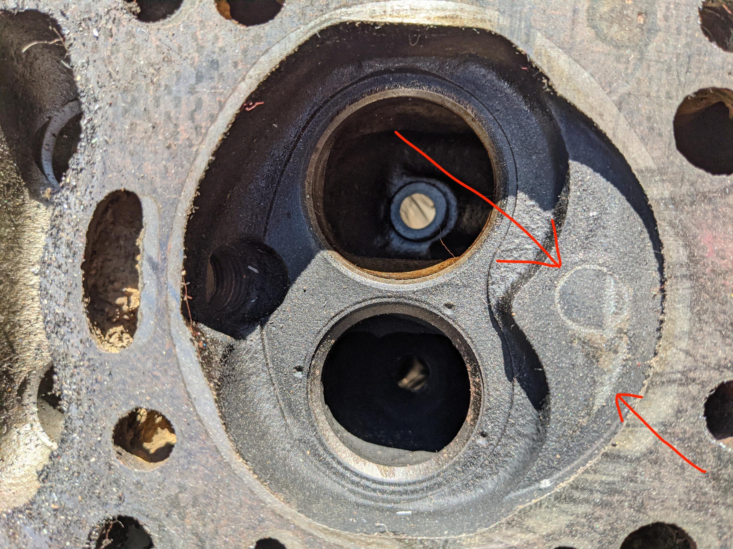
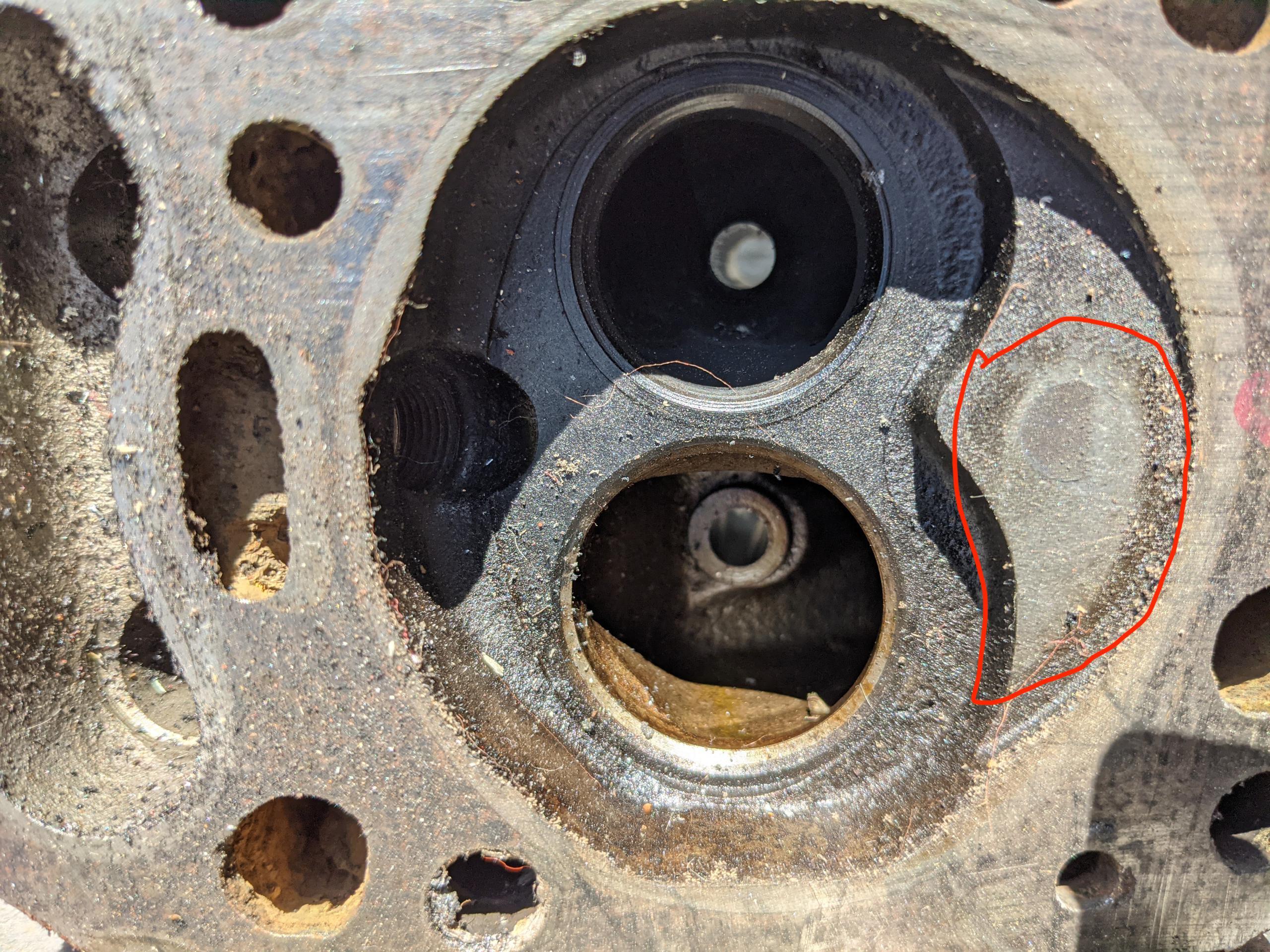
Head Shaving (milling)
It is common to mill cylinder heads to clean up surfaces or to raise compression. There’s nothing unusual about this head in any way, but everything has limits… and the owner of this engine found it the hard way. I bought this newly-built engine for cheap because it had a slight rap, which turned out to be pistons just kissing the combustion chamber. Too much metal had been removed from the head surface, an estimated .050″. I don’t have a hard limit to give you but it would be easy to derive from this knowledge and these photos showing precisely where the least-clearance is. Frank has had a head shaved 0.020″ to raise compression from 8.7:1 to approximately 8.9:1.
If you decide to mill a head (or deck) be sure to use clay to determine how much room you have. At this great age I would not make assumptions about prior work done — measure. The head (and/or block deck) may have been milled a time or two already due to warping from overheating or an attempt to gain performance.
Head Installation
To install the cylinder head onto the block, use guide studs, don’t drop the head onto the sealant-coated gasket and slide it around to locate the holes. If you’re using the recommended ARP studs, install one in each end of the block and use those as guides, then install the studs. If you’re using stock bolts then get lengths of threaded rod or chop the heads off long bolts to use as guides.
Assembly
At the factory the bodies were set over the engine and transmission assembly on the line. Preventing easy insertion from above is the front welded-in cross-brace, just behind the radiator top tank. Mine had long ago been hacksawed out, not un-common. With it out of the way top-insertion is relatively easy, but you lose some body stiffness. This is an unnecessary modification. It’s much easier to remove and install the engine the way AMC (and earlier Nash… this is basically the same chassis as the 50-55 Nash Rambler) from the bottom. It’s not hard — remove the hood, drain and remove the radiator, attach engine hoist to engine, then take the bolts out of the front and rear crossmembers (crossmember to body) NOT the engine mounts! Lower to ground and detach hoist. It’s nice to have a furniture moving dolly to lower the engine on. Attach hoist to body via the crossmember mounting points and lift body. It’s not that heavy without the engine and transmission, but the upper cross-brace WILL NOT support the weight of the body. Support the body with jack stands, move the hoist, and slide the engine out. Moving the body or engine is the hard part. A large furniture dolly under the engine or two smaller ones under the jack stands helps. If you have a lift it’s even easier — support the engine, unbolt the crossmembers, lift car. To install reverse the process. Frank’s done this many times — it’s actually much easier than trying to coax the engine and trans out from the top. If you’re rebuilding the engine taking the head off before removing the engine and installing after the engine is in makes it easier — the body doesn’t have to be lifted as high. At the least take the carburetor off first. Of course that’s not necessary with a lift.
Website contents, unless otherwise specified, © 2025 by Tom Jennings and Frank Swygert. Permission is granted for personal use with no renumeration. Corporations or any legal organization or their agents (employees or consultants or other relationships) expressly prohibited without written permission.