
Frank’s Brakes
11-10-2025 by Tom Jennings, edited by Frank Swygert (instructions written by Frank)
|
 |
INSTALLATION INSTRUCTIONS
Below are partial instructions, to give you a general idea of how it goes together; please download the complete instruction sheet above, which contains detailed information on specific parts, pads, master cylinders, proportioning issues.
1999-2010 Honda Accord V-6 Front Disc Brakes on AMC Vehicles
PROCEED AT YOUR OWN RISK! Brakes are probably THE most important safety equipment on your car. It needs to go, but if you can’t stop you have a real problem! You are modifying the brake system and must take full responsibility for those modifications. This modification has been tested and found to be safe, but the maker of these brackets/kit is not doing the installation and cannot be held responsible for your installation or parts used. There is no warranty on any parts save the brackets themselves, and that warranty is
limited to replacement of a faulty bracket. The maker of these brackets/kit is in no way responsible for any damages or injuries even if the bracket should fail.
If you are not in agreement to this return the brackets for a full refund (minus shipping). In these instruction the maker is assuming you have a basic understanding of brake systems and know how to install and remove brake drums, calipers and pads and how to bleed brakes. Any variation to standard procedures will be noted.
I hadn’t intended on writing anything but simple installation instructions, but the more I thought about it the better a general primer on brake some components seemed to be in order. See Addendum 1: About Master Cylinders and Addendum 2: About Proportioning Valves for more information.
STEP 1: PREPARE HUBS FOR ROTORS:
1. If you have drum brakes, remove the drum from the hub. This is done by first removing the studs (lugs). If you do not intend to re-use them they can be driven or pressed out. Make sure you support the hub from the rear so as not to warp it. You must take extra care to remove the lugs if they are intended to be re-used. A swedge cutting tool can be used, but will ruin the threads on the studs. If using new studs take an original to an auto parts store and match them. The studs are 1/2”-20 threads. The knurl diameter is typically 0.640” or 0.625” – measure the originals! The following Dorman studs should work, depending on knurl size:
| 610-225.1 – 0.640” knurl | 1-3/4” length* |
| 610-154.1 – 0.625” knurl | 1-25/32” length (1/32” over 3/4”) |
| 610-219.1 – 0.625” knurl | 2” length |
| 610-277.1 – 0.625” knurl | 2-1/4” length |
*If a longer stud is needed the hubs may have to be drilled for Chrysler style 0.680” knurl. I couldn’t find a ready source for longer 0.640” knurl studs. Knurl hole size should be 0.006-0.016” smaller than knurl. A 43/64 drill bit works for 0.680” knurl. ARP studs have an underhead radius. The knurl hole must be chamfered 0.25” to clear radius and prevent stud failure.
2. The outer edge of the drum brake hub will need to be turned down so that the Honda rotor will fit. It doesn’t need much taken off. This can be done on a brake lathe or a standard lathe. DO NOT attempt to use a grinder! Material must be taken off evenly around the circumference or balance will be affected. The outside diameter of the hub should be turned to approximately 150mm (5.90”). If having a machine shop do this send a rotor with the hubs and just have them turn the hub to fit. Unless you are replacing the bearings MARK THE
HUBS AND SPINDLES so the hub goes back on the spindle it came off of. I usually spray one set with paint on the base and hub, and leave the other unmarked. The important thing is to not get the outer bearings mixed up as the bearing “wears in” to the race. The rear race and bearing will stay in the hub as long as the grease seal hasn’t been removed. Don’t change the grease seal until ready to assemble. Clean and grease wheel bearings before installing hub.
3. If you are making hubs from a worn AMC rotor you will have to do some fitting. First cut the rotor off. This can be done with a grinder, but best done on a lathe. After the rotor is off the OD must be turned down to approximately 150mm (5.90”). If you used a grinder to remove the rotor portion make sure that area is turned down evenly or there will be balance issues. Any machine shop with a lathe can do this. This URL describes what needs to be done:
https://www.practicalmachinist.com/forum/threads/help-cutting-down-brake-rotor-hubs.256216/
The same care needs to be taken as far as mixing the bearings (unless the bearings and races are going to be changed) as with a drum hub – mark at least one.
STEP 2: INSTALL BRACKETS:
Install Brackets
- The hubs should be off since Step 1 is preparing the hubs.
- Remove the four bolts holding the spindle and brake backing plate (or dust shield if disc brakes).
- Two of those bolts also hold the steering arm on. Make sure you note where the steering arm mounts.
- Measure the length of the four bolts. There are usually two the same length, in pairs (only two different lengths). Measure from just below the head to the end. You will need four new Grade 8 bolts at least 3/8” longer than the factory bolts. 1⁄2” longer is fine, bolts are usually stocked in 1⁄2” increments. These need to be 7/16”-20 threads (fine threads). The original lock nuts can be used or new nuts with lock washers may be used. Internal toothed lock washers are preferred as they are thinner than traditional split ring lock washers. If using split ring type make sure the bolt is long enough. If you had to use 1⁄2” longer bolts they should be long enough for split ring lock washers. You may also use nylon insert lock nuts.
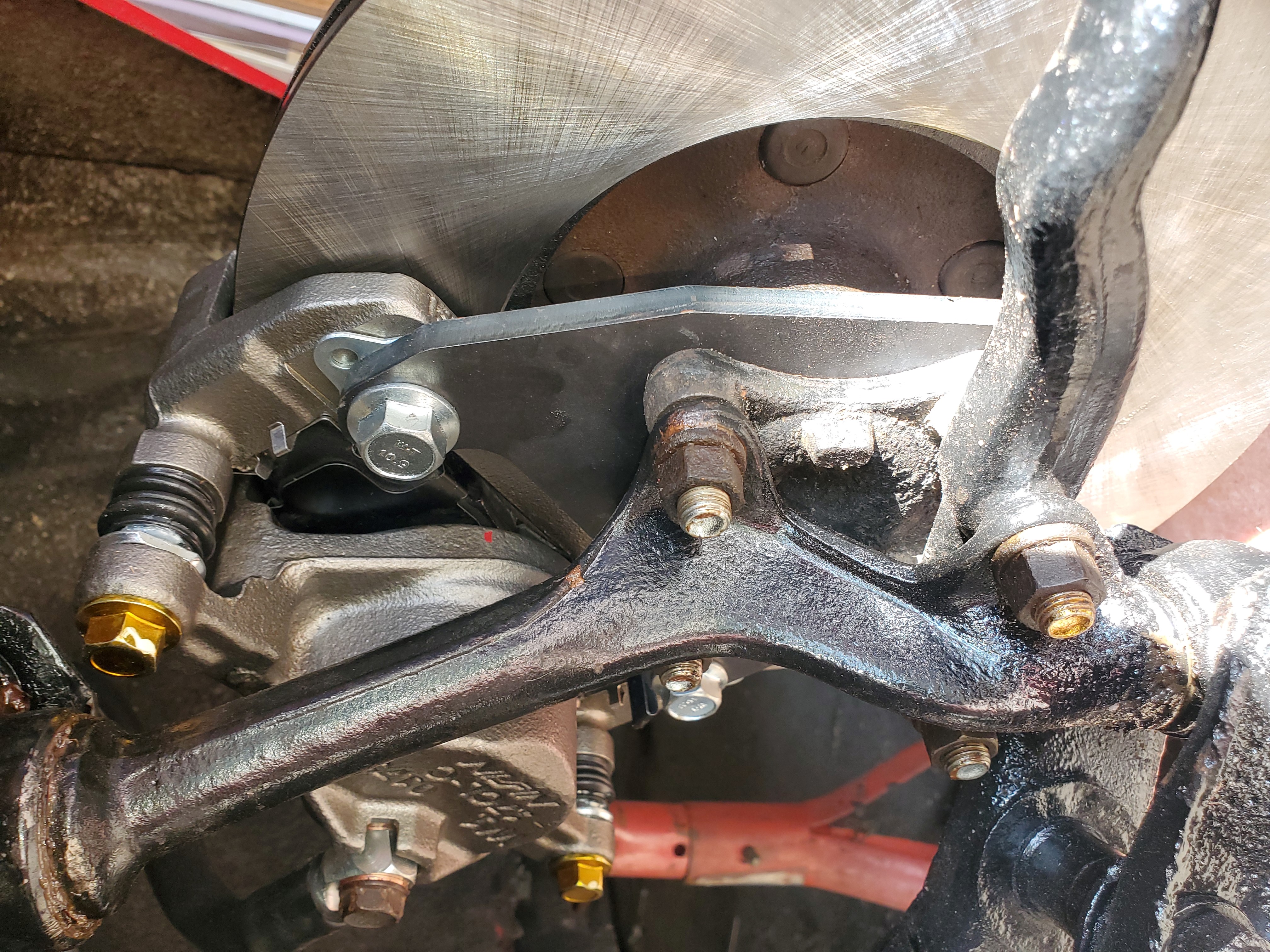
- Reinstall the spindle minus the backing plate (or dust shield) with the brake bracket ON TOP of the spindle. The bolts go through the bracket, through the spindle, then through the steering knuckle. Make sure the steering arm is in the correct location.
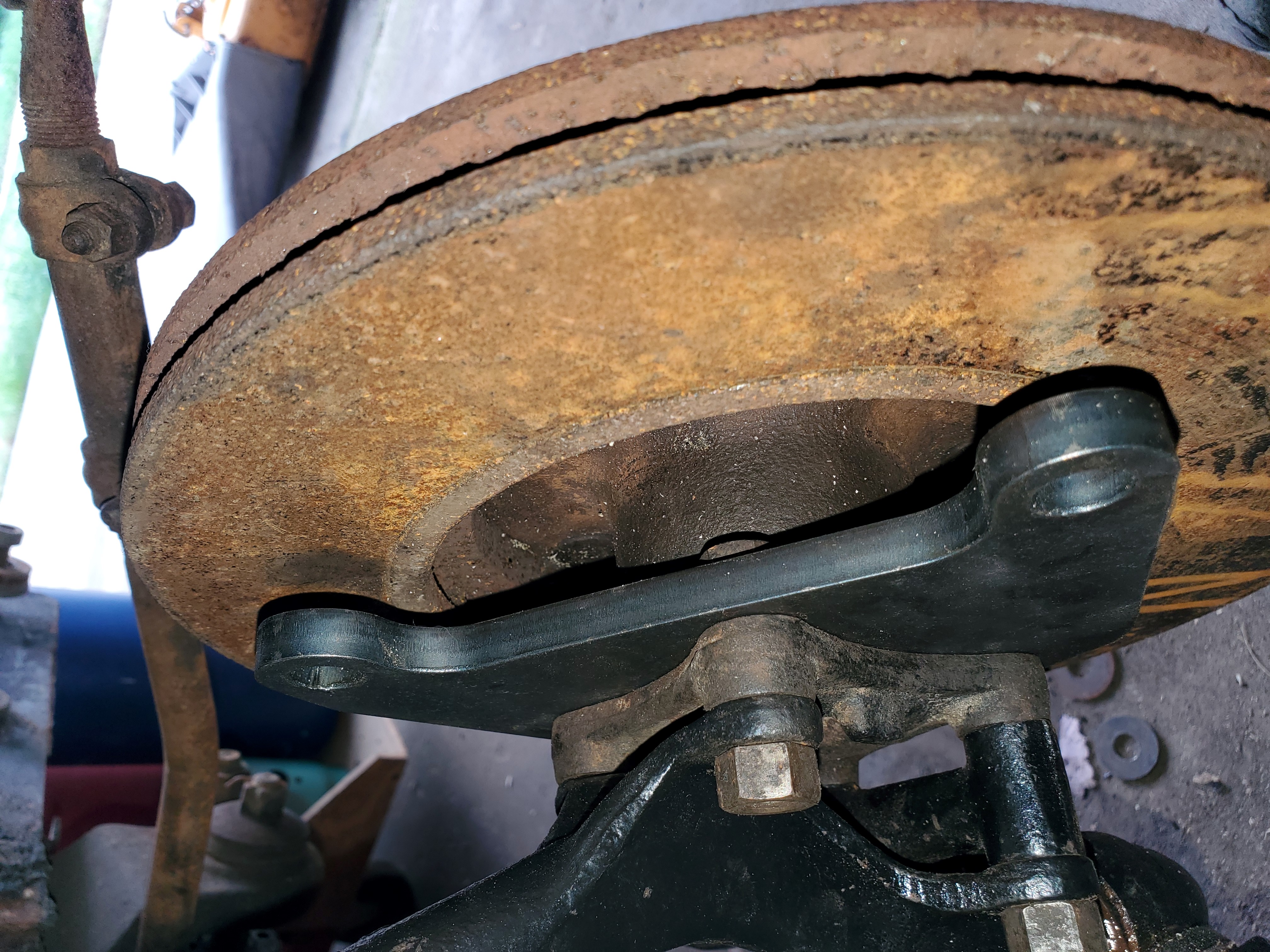
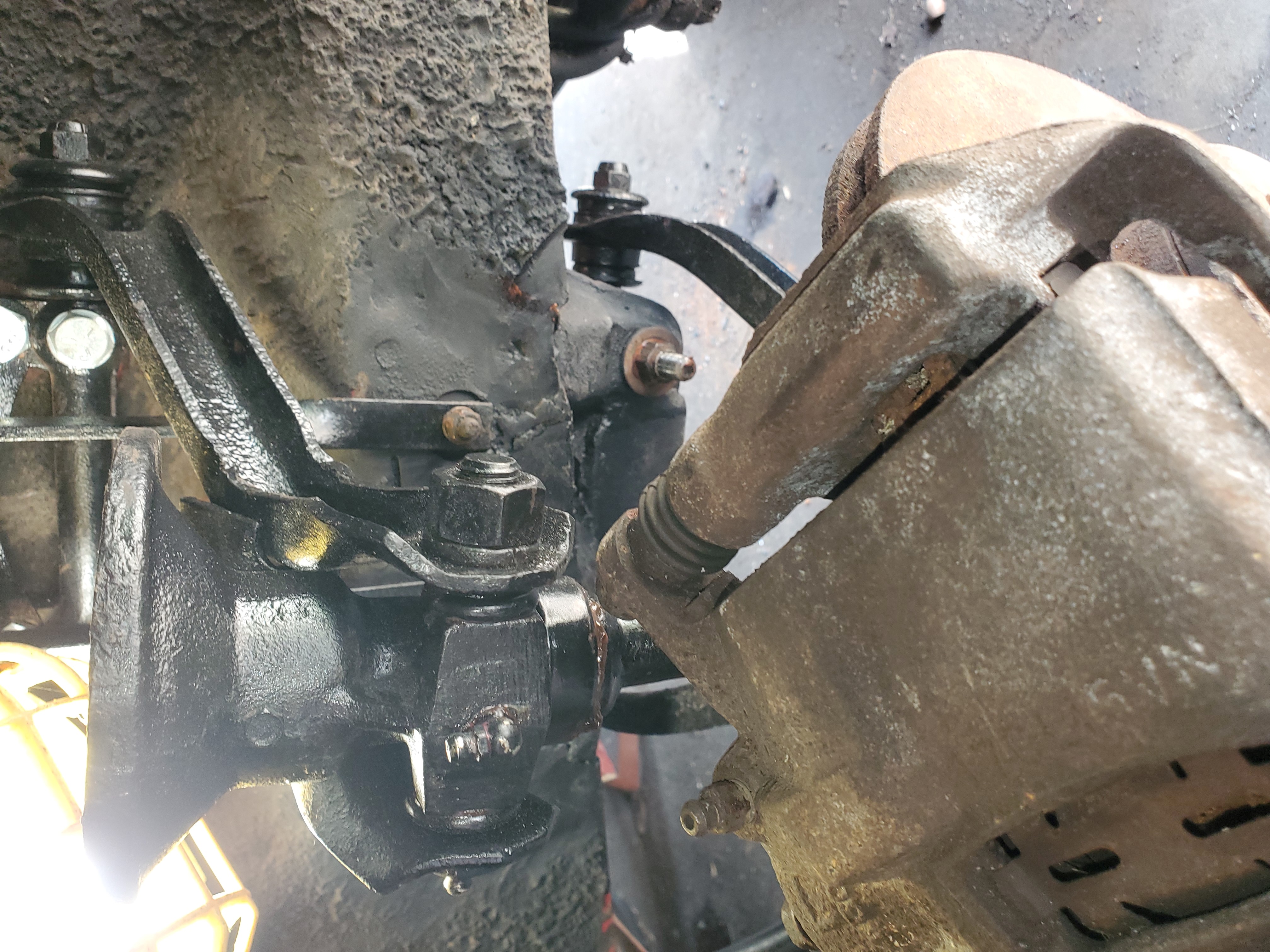
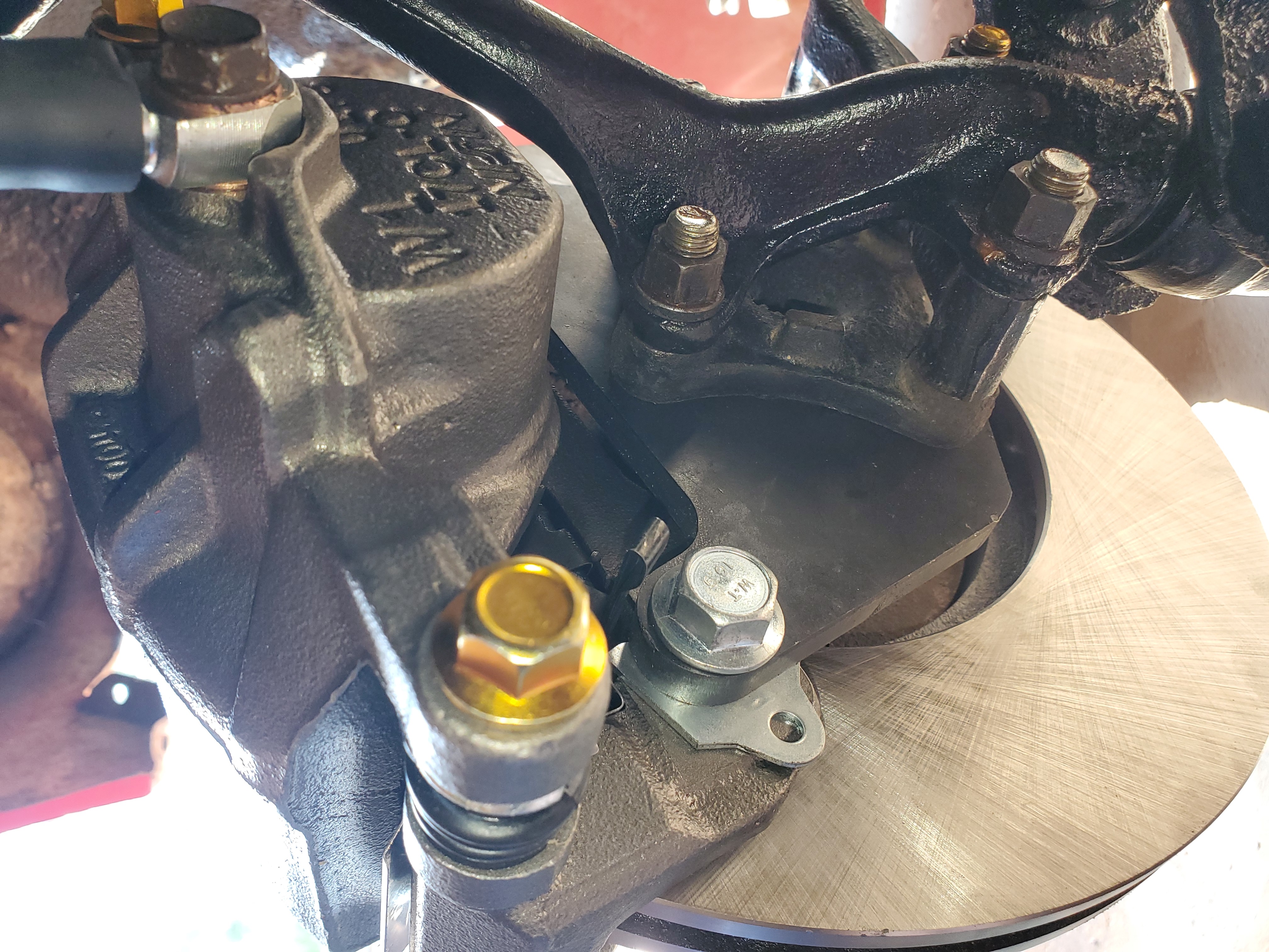
- Calipers to the front or calipers to the back? Good question! On some cars, like the 58-63 American, the caliper must be positioned to the rear for clearance purposes. On most cars it simply doesn’t matter. The photos show the bracket mounting the caliper to the rear (61 American is the test subject). The change to front mount simply swap everything to the other side – bracket and caliper. Braking force and forces on the bracket are the exact same in either position. Install one side then check and make sure everything clears
by turning the steering all the way to one side then the other. Remember to consider where the caliper will be when the suspension is compressed (load on car and further up, such as when you hit a bump) before deciding which way to mount the calipers. Also note that the bleeder screw must be on top of the caliper. - Brackets are now installed.
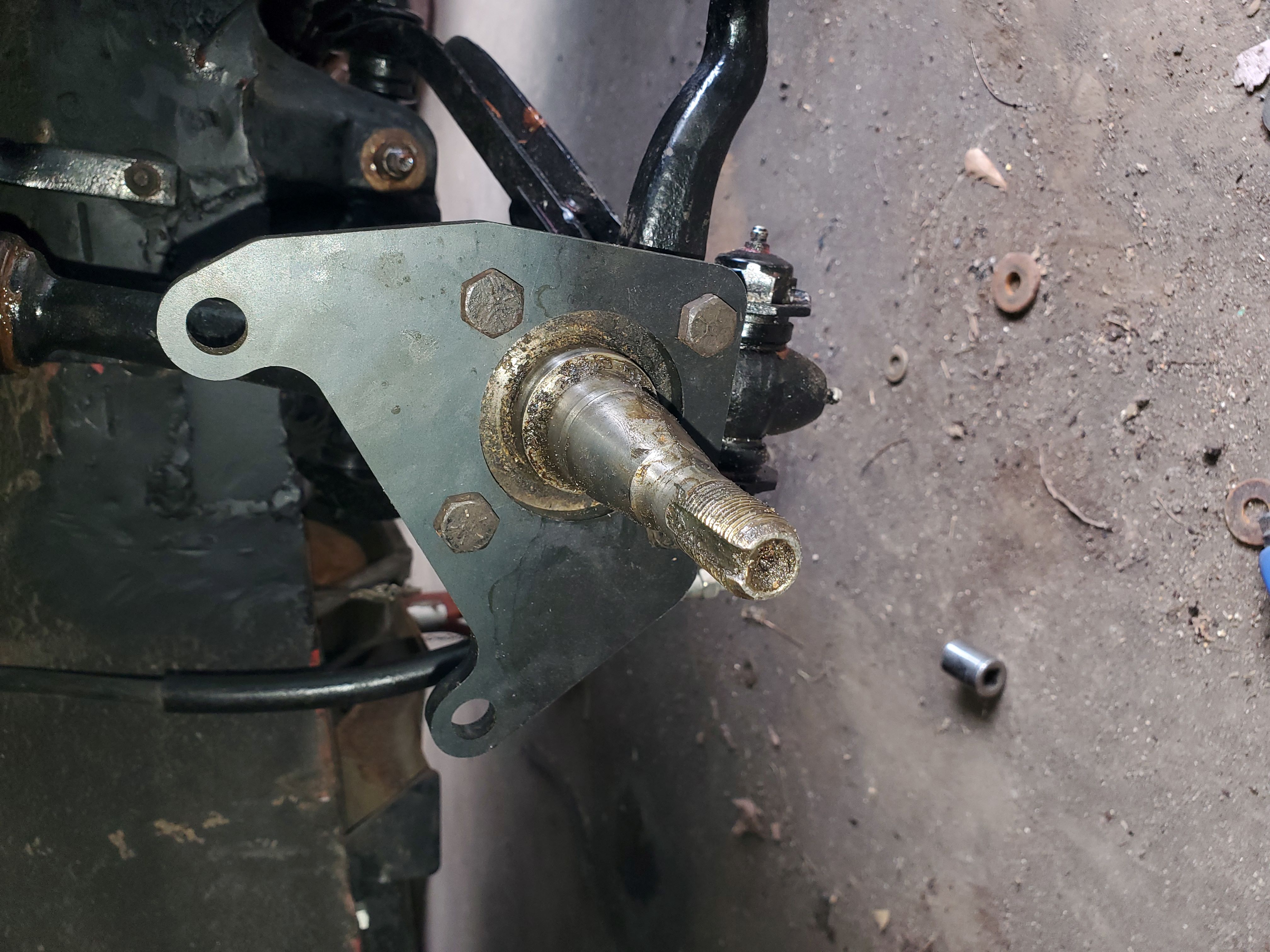
Bracket on 1961 American
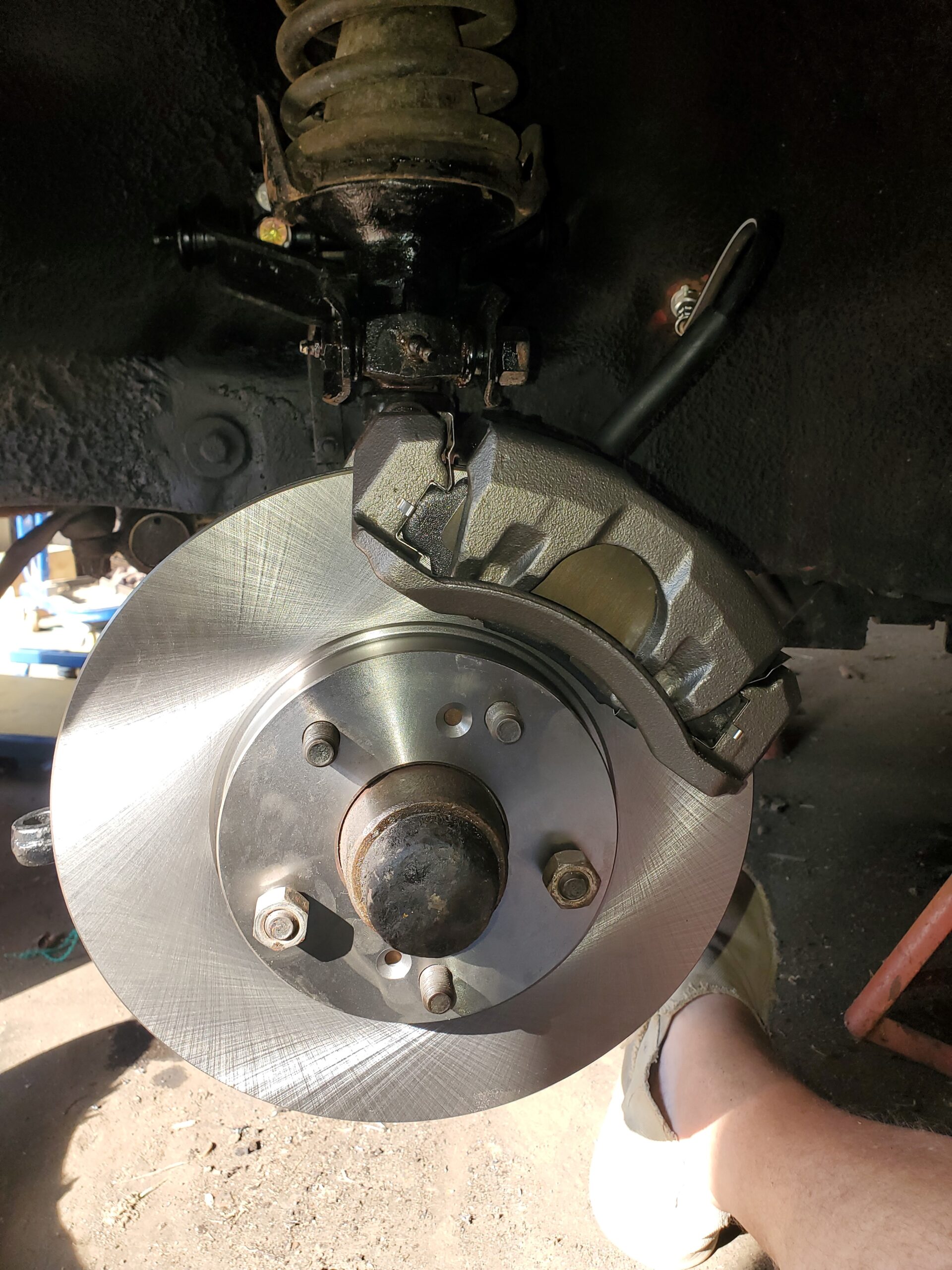
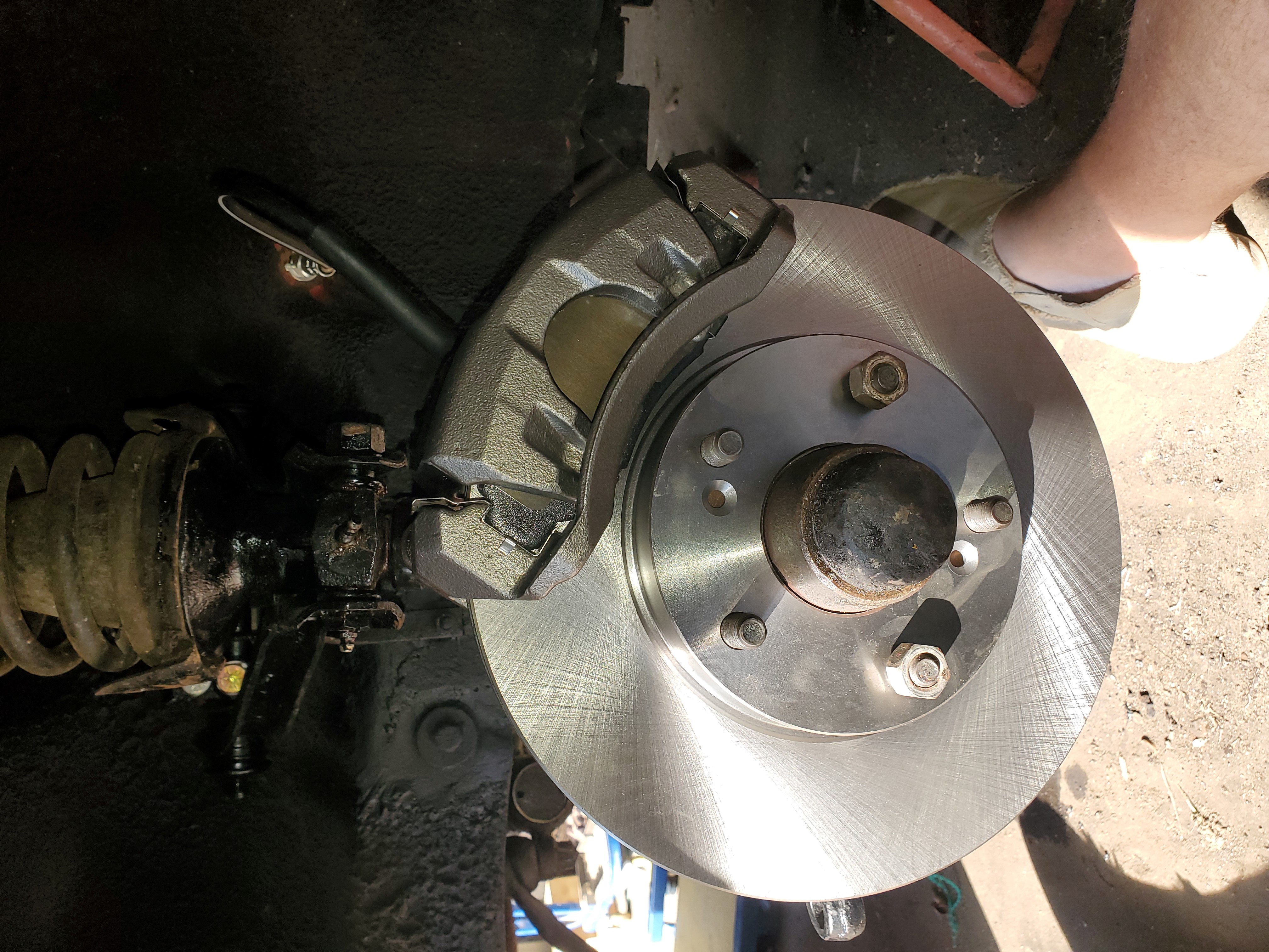
STEP 3: INSTALL HUB AND ROTOR
- Install hub. Hub installs as it would with drum brakes. Grease or replace wheel bearings and replace rear seal as necessary.
- Install rotor. Rotor is hat type and simply slides over the wheel studs. It should lie flat against the hub.
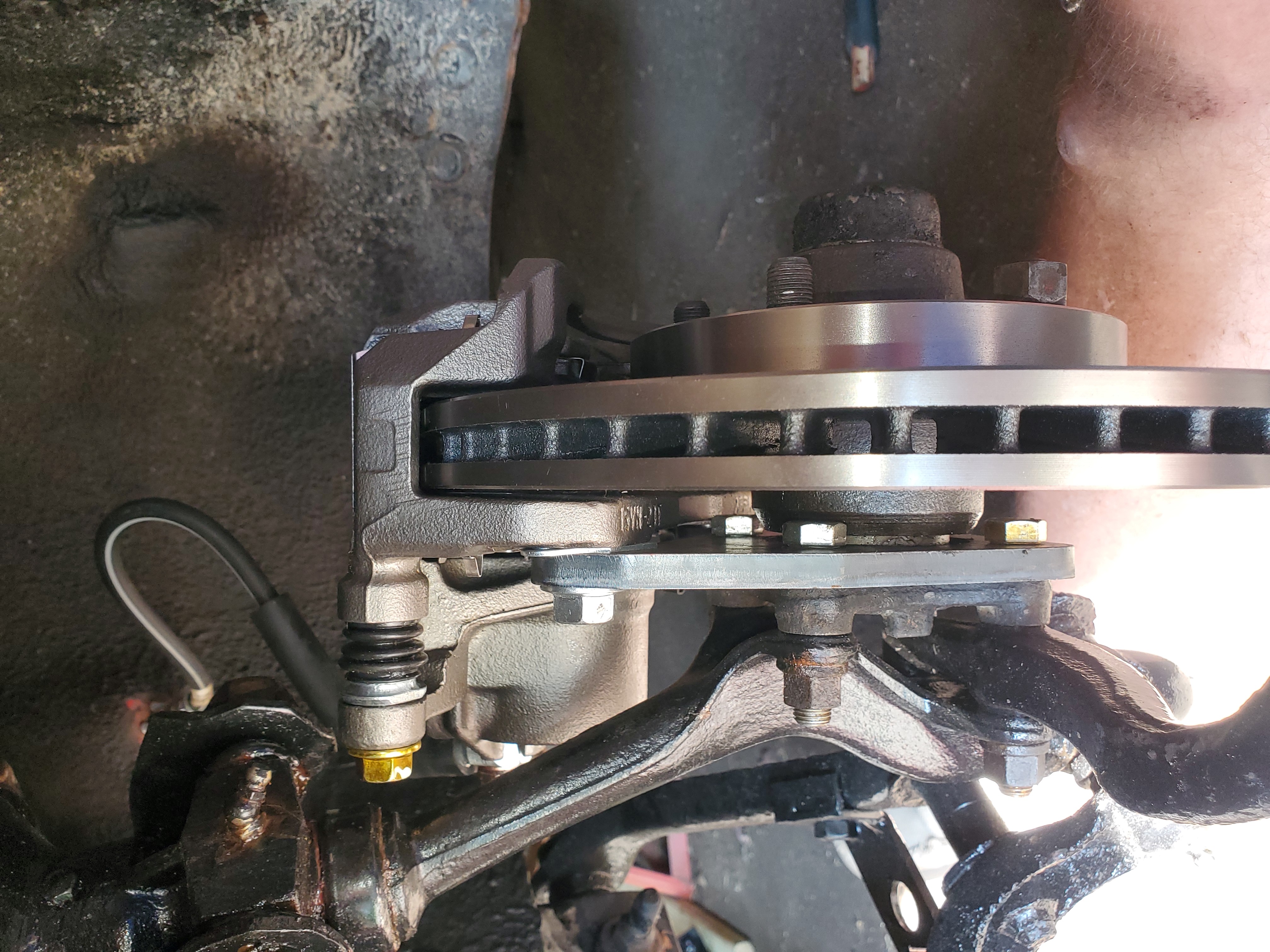
- Now install the caliper. Caliper mounting bolts are M12-1.25×21. These work with a 1/16” spacer (one washer), but will need to be longer if more spacing is needed. They are threaded into the caliper. It is best to start with the lower bolt. Don’t tighten as it will have to come back off once spacing is determined. Again, note that the bleeder screw must be on top of the caliper.
- Check for spacing between the caliper and bracket. On the 58-63 American one washer (about 1/16” thick) was required between the caliper and mount to center the caliper over the rotor. It doesn’t have to be perfectly centered, the caliper pistons will self adjust, but there isn’t much play as you can tell from the photos. Only graded washers (Grade 5 or Grade 8, metric 8.8 or 10,9) should be used for spacers – common hardware store ungraded washers are softer and can deform. Body or alignment shims may be better and come in precise thicknesses from 1/64” to 1/8” (stack for desired thickness). Shims will be a bit harder to install, but may be necessary depending on thickness needed. Shim kits are $10-15 on Amazon, $10 at Harbor Freight.
- Once the calipers are installed connect the brake hoses and bleed the brakes.
Detailed information including part numbers are contained in the downloadable instruction sheet!
More images
Deprecated: File Theme without comments.php is deprecated since version 3.0.0 with no alternative available. Please include a comments.php template in your theme. in /home3/amcmagc1/public_html/wp-includes/functions.php on line 6170
Leave a Reply