written by Tom Jennings 12-13-2023, edited by Frank Swygert 06-12-2026
Block, Crankshaft and Connecting Rods
Crankshaft, connecting rods, pistons, oil pan, side covers, harmonic balancer, installation.
Brand new NOS block shown below.
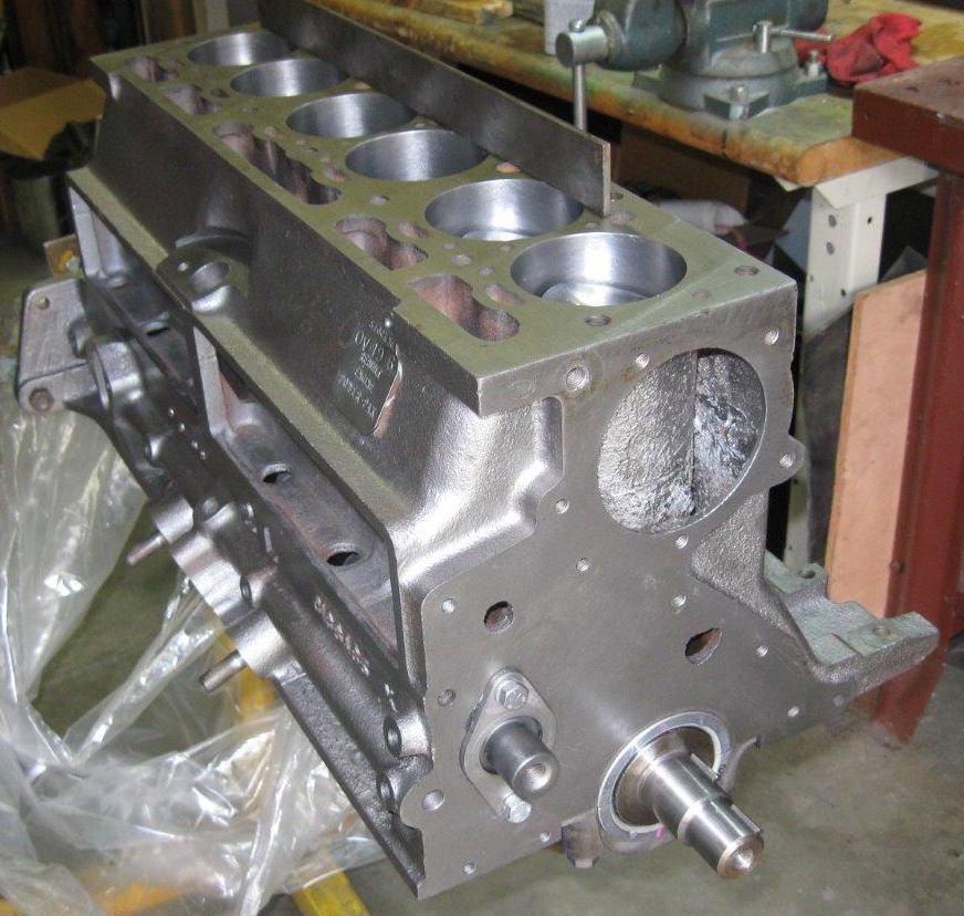
Block Variations
195.6 OHV cast iron engine blocks are mostly interchangeable. In 1957 the water pump moved to the front of the block (was behind the generator, pumped into the center side of the block in 1956, as were all earlier L-head models — there is still a casting boss for the pump visible there). In 1961 cam bearing sizes changed. In 1963 a timed top-end oiling feature was added and engine mount bosses were added for the new 1963 Classic/Ambassador chassis which used mid point mounts instead of four corner mounts (Tri-Poised Power – two engine and one transmission mount). Finally, in 1965 a full-flow oil pump and filter was added, the last year of production (there may have been a few replacement engines made in 1966).
Despite these changes the blocks interchange from year to year, with the obvious exception that the pre 1963 blocks do not have the bosses for the mid engine mounts. 63-65 blocks will, however, mount in earlier chassis simply by swapping the front mount plate from the earlier block (behind the timing cover) to the later, and using the older bell housing with the two rear mounts. A not so obvious exception is that the 65 full-flow oil pump version can’t be used in the 58-63 American chassis due to clearance issues — not enough room on the right side for the oil filter. It can be used in the earlier big car chassis though. The full-flow oil pump cannot be bolted to the older blocks. Well, it can, but it would dump return oil on the ground! The block was modified for an oil return near the bottom of the block. The older pump also can’t be used on a full-flow filter block as there would be an opening into the lower portion of the block.
The differences in engine block lubrication are covered in detail in the OILING section.
Pistons
For his 2010 build Tom got fair quality replacement pistons and rings from Kanter. The pistons were static balanced with a gram scale (most electronic postal or kitchen scales work fine, can be done in ounces). They were not bad to begin with, there were only slight weight differences. Rods and bearings were fine, probably; though connecting rod bearings failed (leading to the 2017 tear down). It seems fairly likely that the failure was due to the collapsed (softened) oil pump pressure relief spring purchased from Kanter.
The pistons for all 195.6 OHV engines are of a domed design. There are variations in ring thickness over the years or from different manufacturers years. To the best of my knowledge the ring thicknesses are:
| Top ring | 5/64″ |
| Second ring | 5/64″ |
| Oil ring | 3/16″ |
The L-head engine’s pistons are flat on top, and rings are all 3/16″. Be careful when buying rings, pistons and other engine parts: parts sellers may list them simply as “195.6” or “196” and either not know or not care about the difference between L-head and OHV versions. We’ve all got the wrong parts languishing on our shelves from not paying attention to details!
Camshaft Bearings
Larger diameter bearings and camshaft-timed top-end oiling
The hard-won knowledge in this section was worked out by www.theAMCForum.com user wittsend. I’ve placed it here (Tom), edited, with his permission.
Nash then AMC, went through three different camshaft bearing designs in the 1940’s through 1965. From Nash through 1960, late-1961-up, and 1963-up. The 1960-65 AMC Factory Parts catalog (Group 1.40) lists only two bearing sets for all (AMC) years starting 1960 when the catalog was published, which could mean that the oldest system isn’t in this catalog.
In 1961 the camshaft journals, and the block camshaft bores, were enlarged. All engines after this change have the same diameter. Bearing inserts for this change pertains to 1961 and 1962 engines.
In 1963, and for OHV engines only, AMC changed the top-end (rocker) oiling system from “full time” (head pedestals fed from a steel tube run up from the main oil gallery) to “timed oil”, where block, camshaft and front camshaft bearing were changed to interrupt the oil flow to about 40% of the previous system. These bearings are the same as 1961-1962 with an additional hole and a gully on the front bearing (all others are the same as 61-62). If you use timed oil ensure you have the correct front bearing. This was done to limit the amount of oil pumped up into the head during sustained high speed operation — something that wasn’t really possible until the mid 60s when a good portion of the US Interstate system had been constructed and the rest was under intense construction. Too much oil in the head can lead to greater oil consumption (oil sucking past the old style umbrella valves — modern positive seals alleviate this) and leaks at the rear of the valve cover.
If you cannot use the correct bearings in a 1963-up block, it is possible and reasonable to revert to non-timed oil and feed the top end from the main gallery. This will require replacing the steel tube feeding the head. Tom’s roadster runs this way; he’s found no downside and runs that engine very hard. You could also modify the older bearing, but getting the hole in the correct position would require careful measuring. If you save the old bearing to copy it wouldn’t be to difficult to do. You can also drill through the oiling hole after the bearing is installed, but be careful not to leave any chips or drill into the threads in the hole. That method would be best used when rebuilding and the crank hasn’t been installed yet — much easier to clean any chips out.
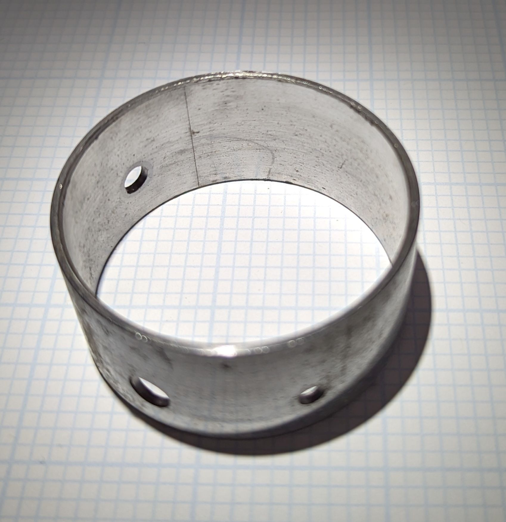
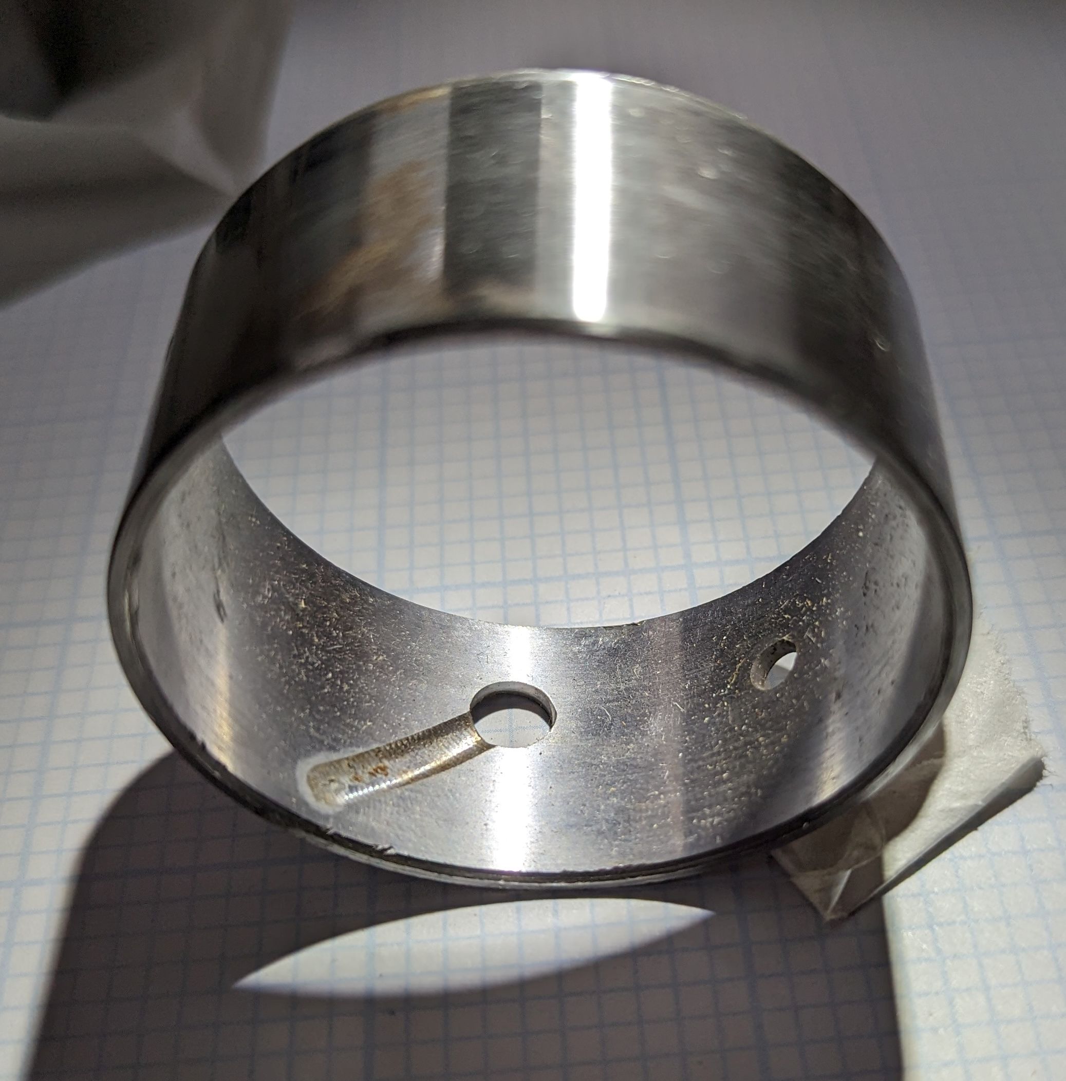
This is the 1963-up timed-oil front bearing. The through-1962 and all L-head bearings will look the same except for the extra hole and gully.
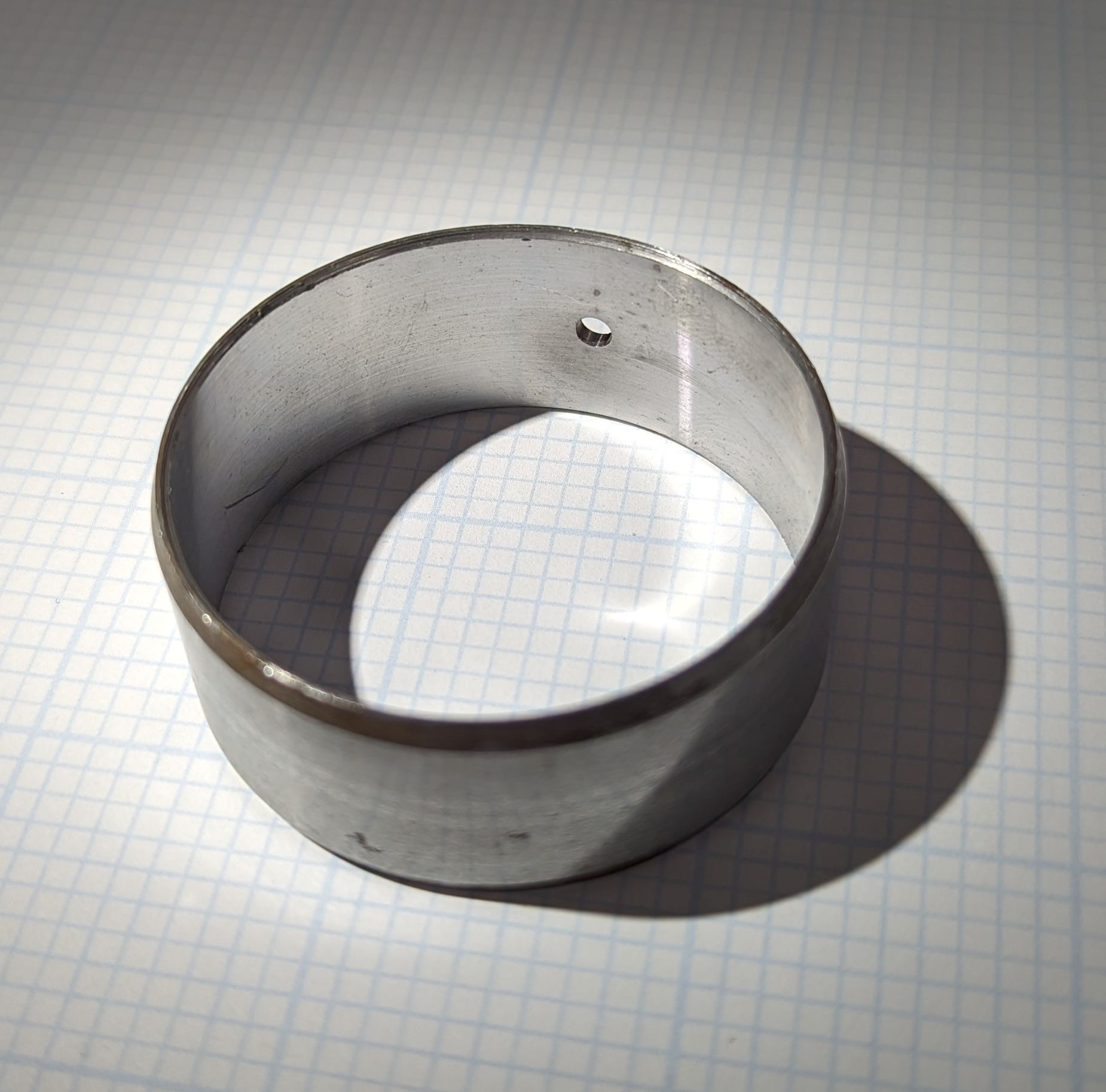
This is the insert for positions 2, 3, 4.
Here are some aftermarket parts numbers to guide you in your search, once again courtesy of wittsend.
| Late 1961 and 1962: |
|---|
| N-5 Dura Bond |
| 1193M Federal Mogul |
| 944CS Michigan |
| SH470S unknown |
| S295P unknown |
| CBS 131 unknown |
| 1963 thru 1965: |
|---|
| N-6 Dura Bond |
| S321P Johnson |
| PSH-529S [2441106] Perfect Circle |
| 935CS Michigan |
| 1219M presumed Federal Mogul |
| SH529S unknown |
| CBS 151 unknown |
Crankcase Ventilation
It is routinely accepted that this engine consumes a lot of oil. In Tom and Frank’s experience most of this is oil mist drawn through the PCV system (or out the road draft tube). Oil consumption increases with operating RPM; about half a quart per day driving 1000 miles at 65 mph and above (2800 – 3000 rpm). This is about cut in half at speeds under 55 or so. A good pcv system hugely improves oil mess and consumption.
Timing Cover
The timing cover of this engine is slightly fussy, but nothing serious.
The timing cover is in two halves; a base plate that bolts flat to the block and a more ordinary cover. The base plate seals to the oil pan. Pressurized oil passes through the base plate, and there is a gasket behind it. On four point mount cars there is a lip on the bottom of the plate for the two front engine mounts.
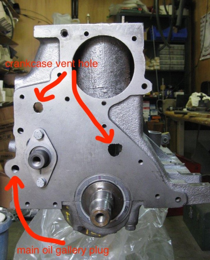
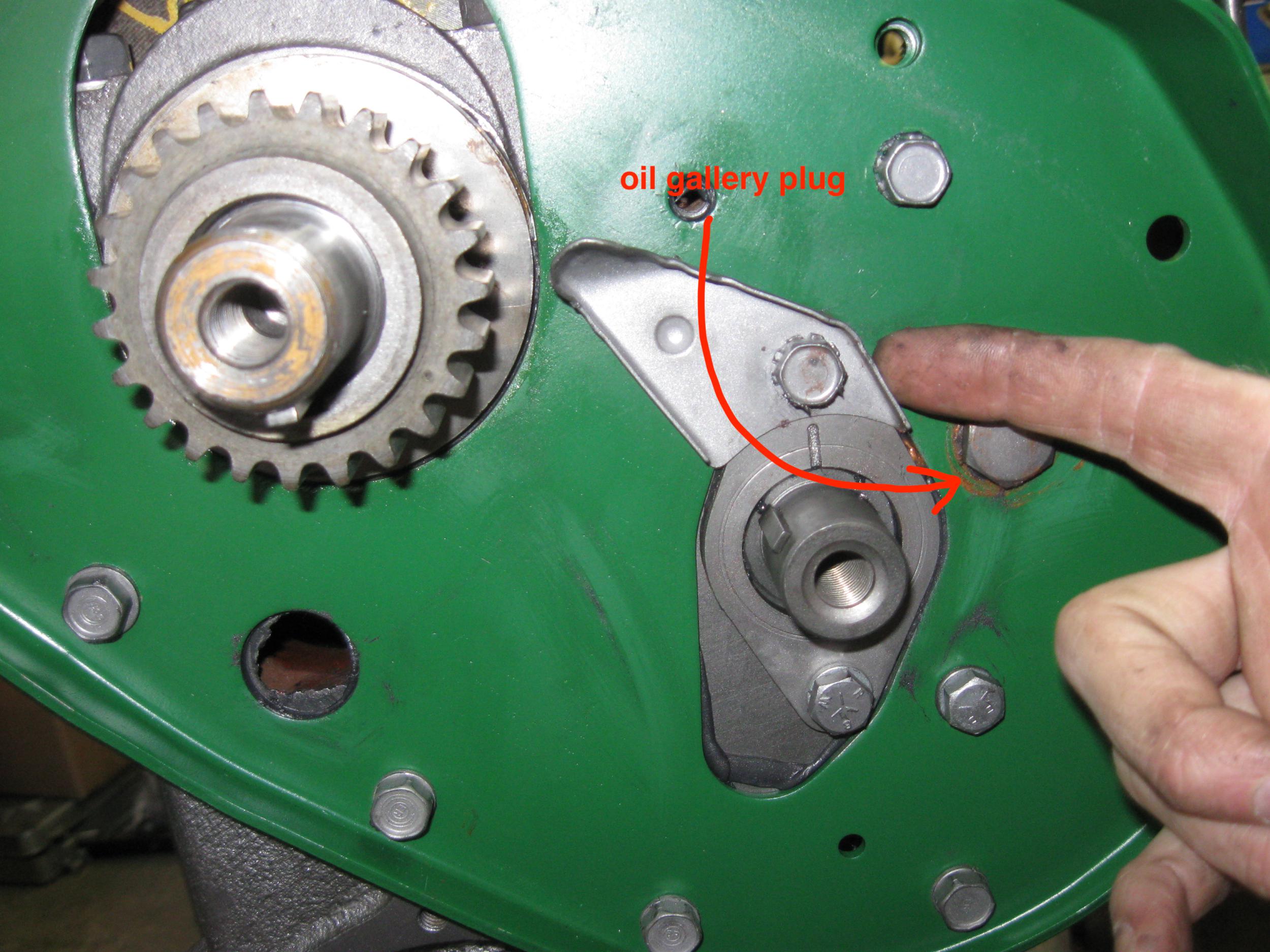
Note that there is a 1/4″ NPT pipe plug in the end of the main oil gallery under the timing cover, and one on the back of the block. It is easy to forget these plugs when reassembling an engine!
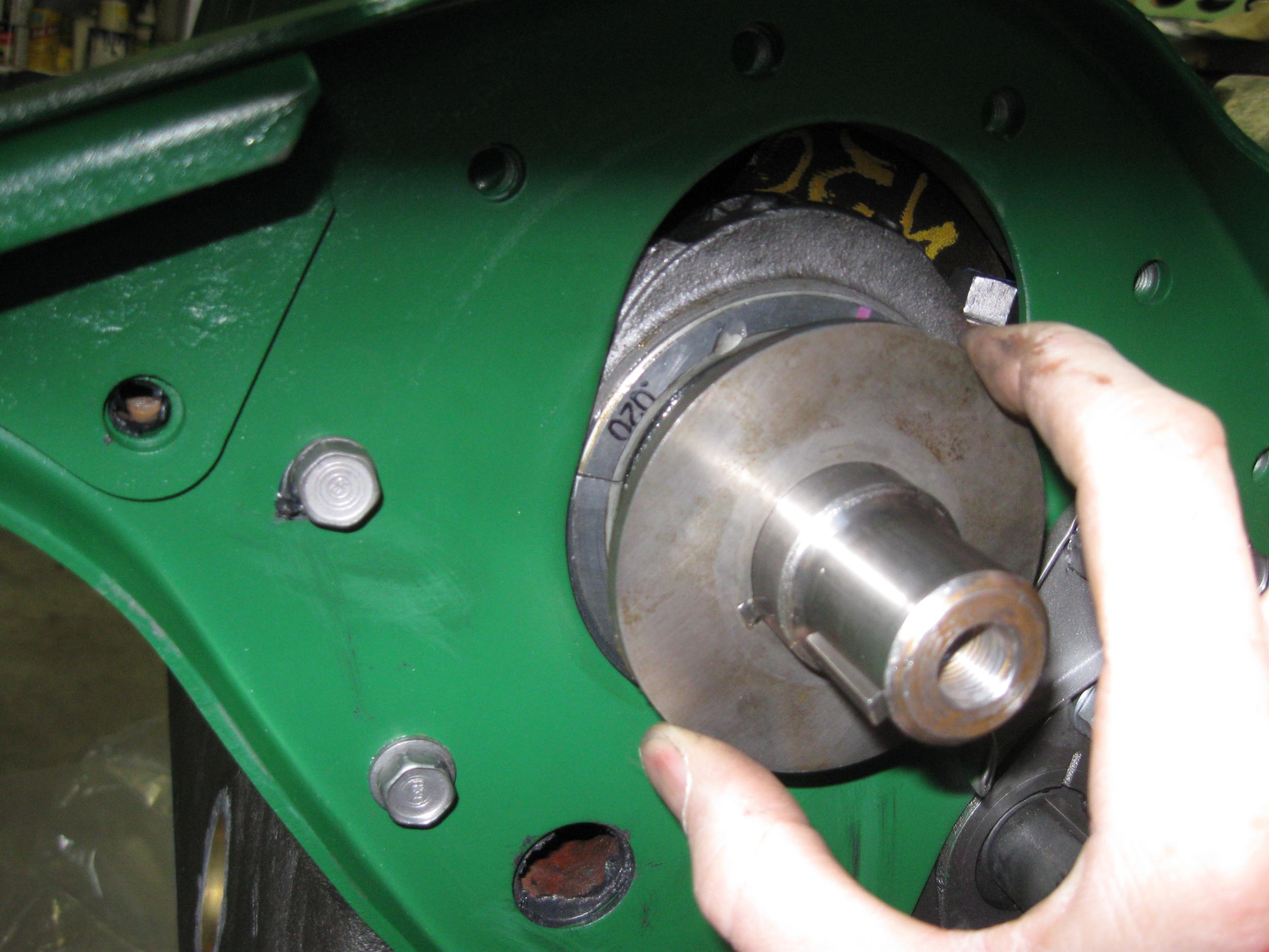
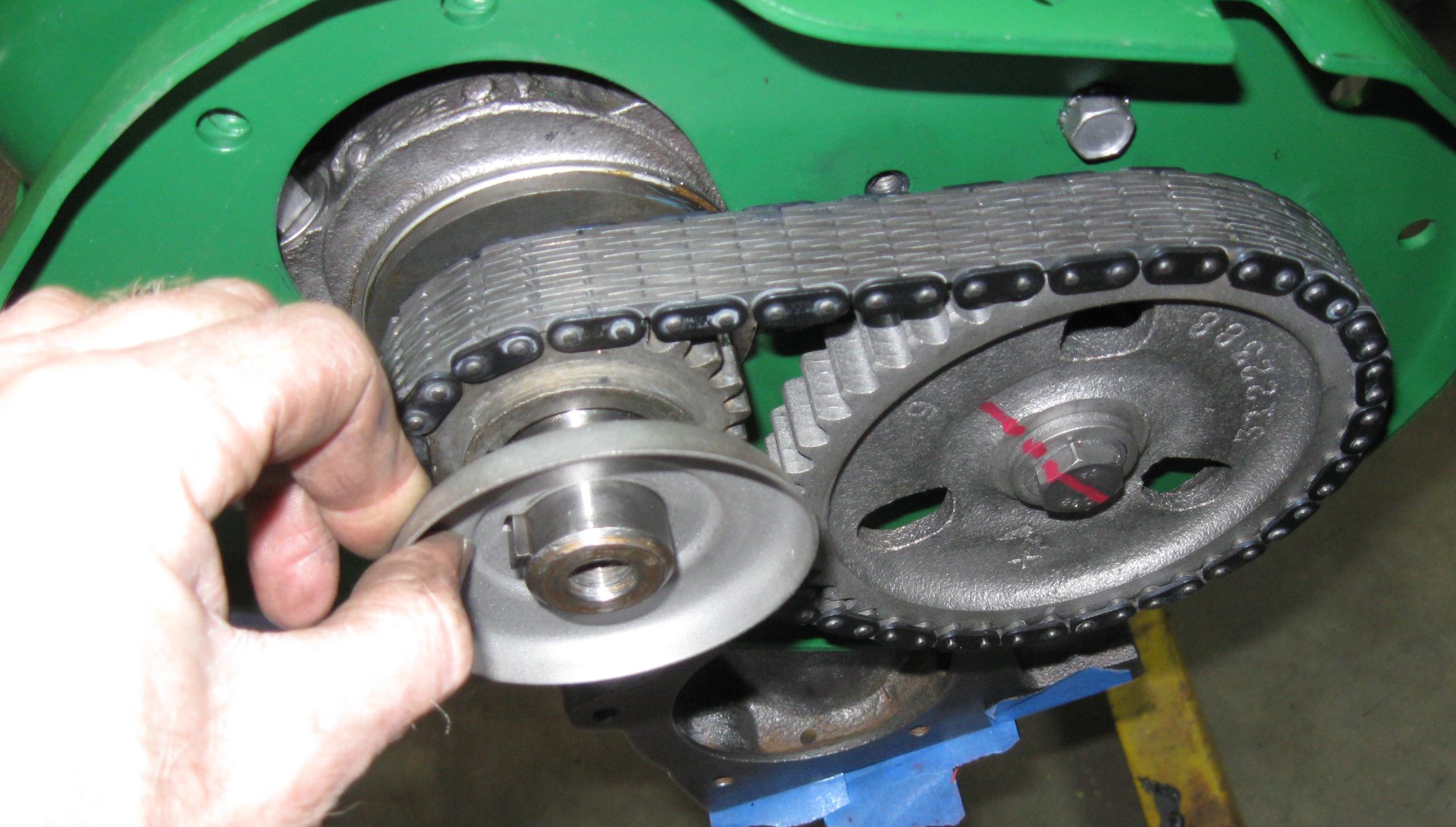
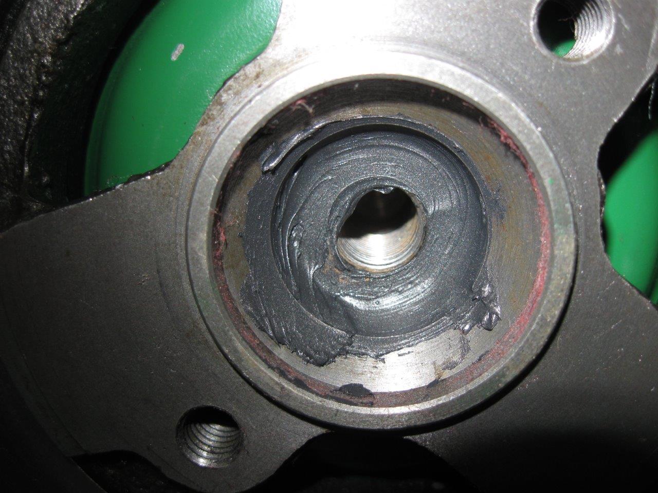
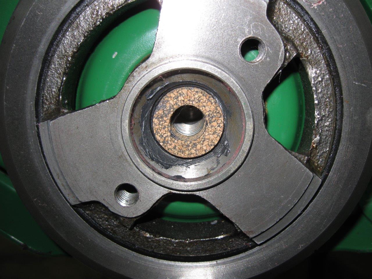
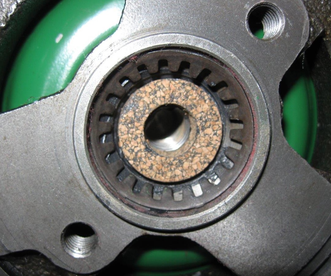
Install the timing area base plate, camshaft retainer, timing chain oil scraper, and the oil slinger onto the crankshaft nose. The slinger is cupped to go over the seal (it can be seen in the fourth photo below showing timing chain installed). Timing chain and sprockets then installs as per the factory service manual.
do not tighten timing cover bolts until you have read all of this section. The final position of the timing cover is determined by the crankshaft seal for the front pulley/damper. Tightening the cover bolts too early may cause the seal to leak.
Press the seal into the timing cover with a socket or something that presses carefully on it’s steel shoulder, not the rubber. The rubber seal must remain perfectly round or it will leak.
Install gasket, sealer, timing cover and most of it’s bolts loosely, so that the cover can slide around a bit. Lubricate the seal in the cover and the damper journal with oil, and slide the damper onto the crank nose (it’s a slip fit). The seal and timing cover are now centered on the shaft. Timing cover bolts can now be tightened, but be warned that on this engine that the oil pan attaches to the back side of the timing cover as well as the bottom of the block; a test fit now is a good idea.
Don’t forget to install the front and rear main oil gallery plugs!
In these photos, the engine is on a stand and shown at various rotations; the big sprocket is the camshaft, the small one crankshaft. Sorry for the dizzying perspectives.
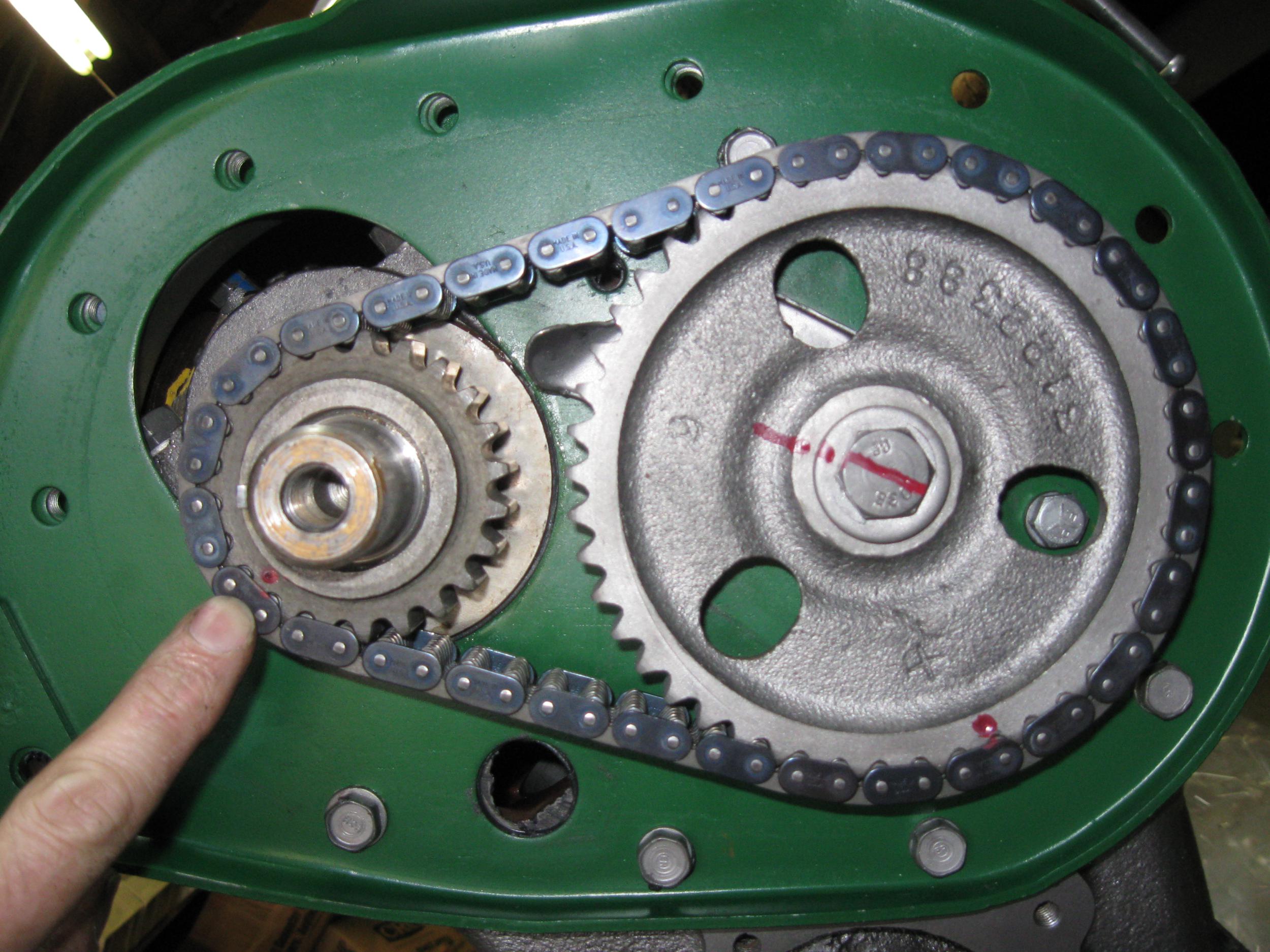
The bracket welded to the front of the timing cover in the photo below is to attach the ford EDIS crankshaft position sensor (reluctor) on Tom’s roadster engine. A “36-1” wheel bolts to the harmonic damper. More on this in the Ignition System section.
The timing cover has a machine screw that serves as the ignition timing mark pointer. They’re often bent or loose and leak oil. Nothing special about this screw, hardware store 10-32. I didn’t record the length.
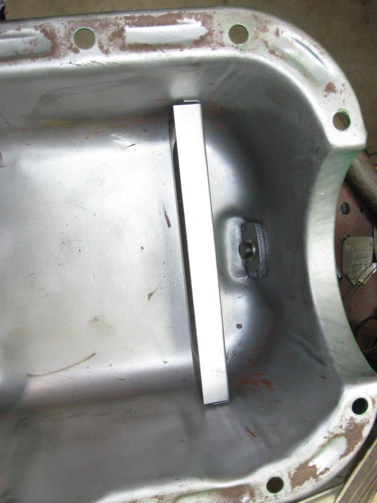
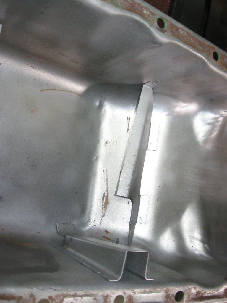
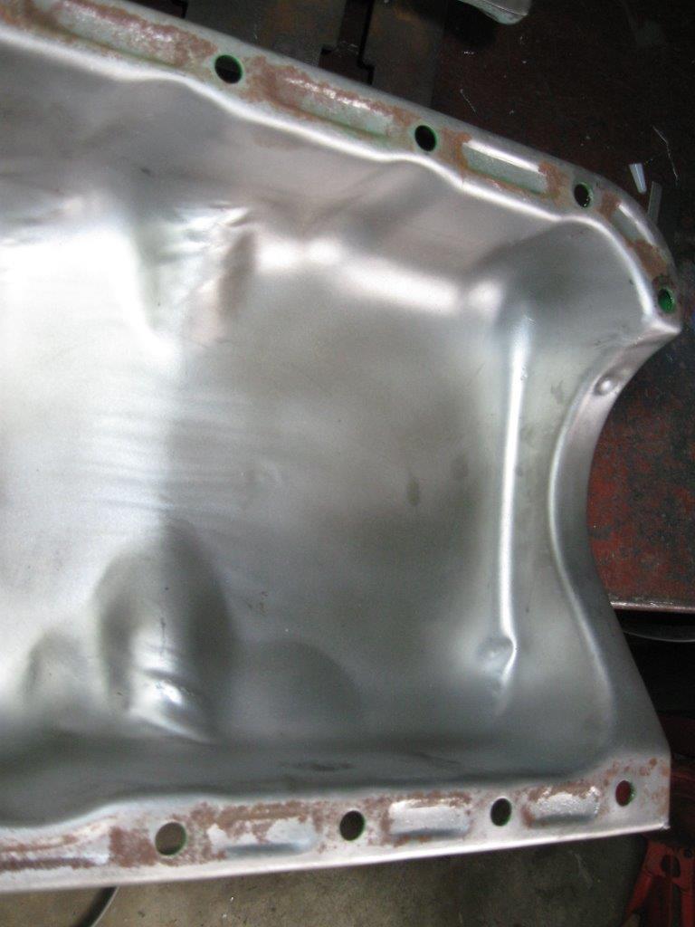
Oil Pan
The oil pan is ordinary enough, with a small baffle at the front to lessen air in the pickup under hard braking. In modern city driving the occasional panic stop does cause a momentary oil pressure drop. All of my engines have done this, it’s alarming but only momentary — it won’t cause any damage.
My 2010 build was assembled with no oil pan gasket, instead sealed with Permatex Right Stuff (#25229 in 3 oz pressurized can, 25223 in 4 oz, #25224 in 7 oz) . It has never leaked. I installed it this way in 2010 and when pulled out of the car for the 2017 rebuild it had not developed even one oil leak. For the 2017 build, in the hands of a professional engine builder, it was assembled more normally with a Best (brand) gasket set. Two years later (2019) there were signs of minor oil seepage in the usual places. Modern engines are assembled with modern sealers similar to Right Stuff, not gaskets.
The Best (brand) oil pan gasket set came with the wrong rear pan seal. I ended up re-using the old rear pan seal, which was supple enough, but I used enough Right Stuff to ensure it would not leak.
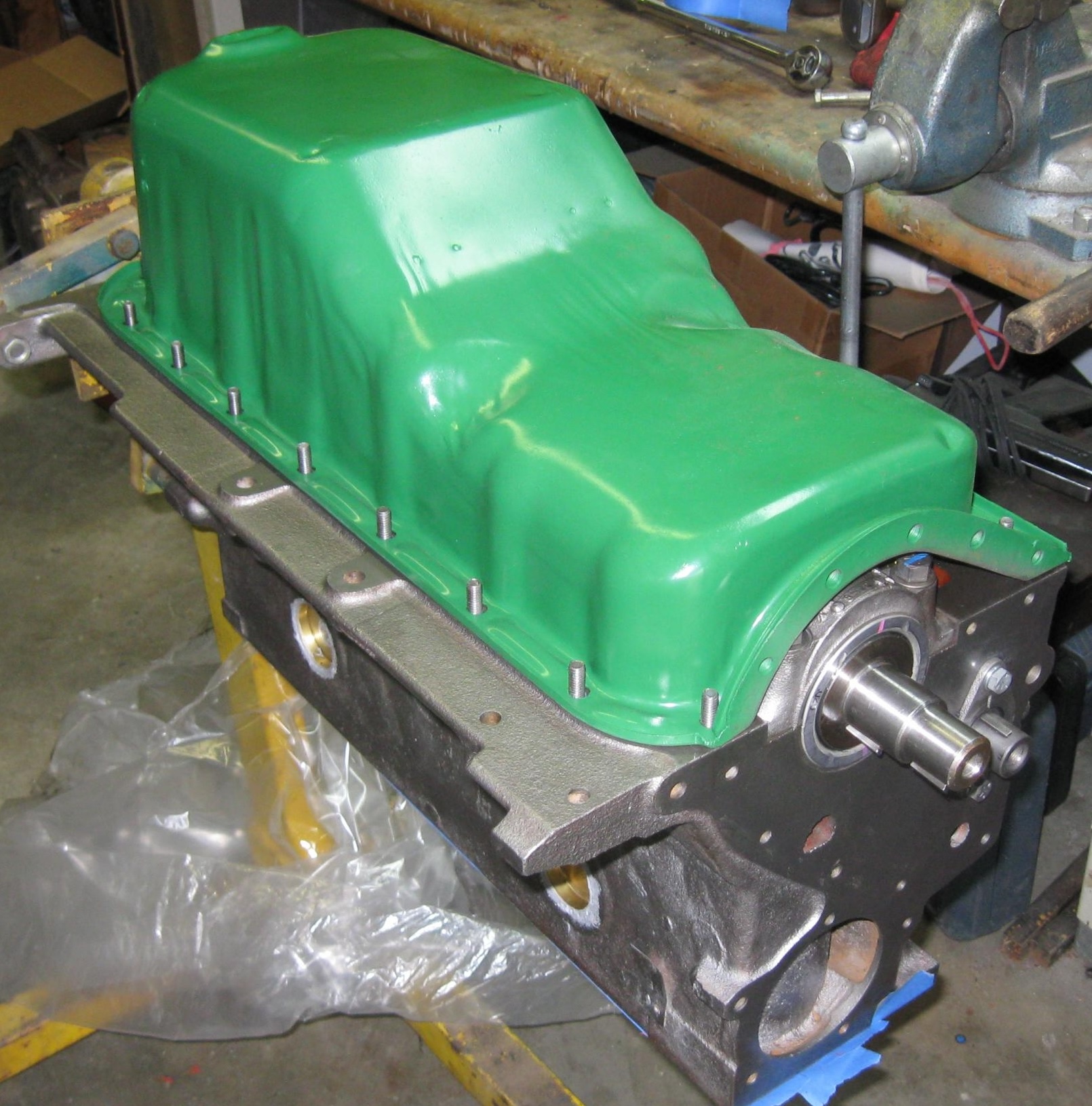
That nice looking drain plug in the first oil pan photo is no accident. I spent a lot of time getting that right. I bought a magnetic drain plug (thanks Nate for the suggestion), and filed the mating surface perfectly smooth.
The oil pan seals to the timing chain cover at the front, which is 90 degrees from the bottom of the block. This requires a back-and-forth tightening sequence to pull it into place. Timing cover installation must be completed before the oil pan can be torqued down.
I was very generous with Right Stuff around the rear main and seal. You should be able to see it extrude between the casting and cap, eliminating yet another leak source. The rear pan seal has Right Stuff under and over it.
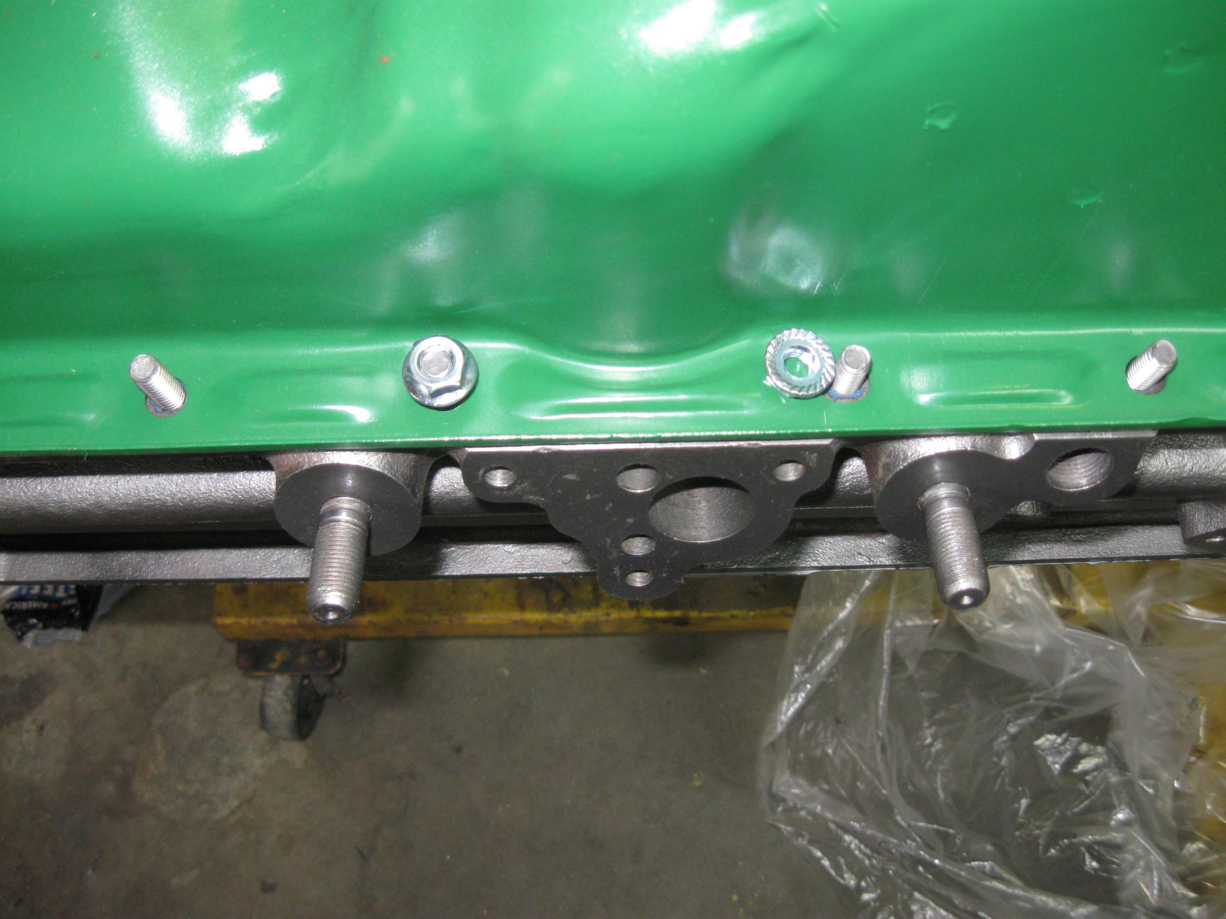
I replaced the pan bolts with studs. In the first photo below two of the nuts are visible, one on one off. The stud system was cheap, grade 5 hardware from MSCDirect. It’s not necessary, but makes it easier to get the pan aligned. I suggest installing at least four studs, two on each side near the ends. The pan cannot be tightened yet, the timing cover base plate must be installed and sealed first. This was done within a few minutes of these photos. The two large studs on each side of the oil pump mounting surface are for the 63-65 side engine mounts.
Side Covers
The very existence of these covers is comical. They’re a vestige of it’s mutation from a L-head (flat-head)– for the flattie, the adjustable cam followers were under there. There is no reason to ever take these covers off. Their only purpose today is to leak oil. I sealed them with Right Stuff and used Loctite Blue Threadlocker on the fasteners.
They are good for one thing though. There is a “shelf” where the tappets come up. There are recesses beside the tappets on this “shelf”. Sludge can collect in this area. It’s a good idea to remove the side covers and clean this area on an old but running engine. When rebuilding it’s not a concern — the block is thoroughly cleaned before assembly. With proper oil changes these areas shouldn’t build up sludge very fast, but it’s possible. It is still a good idea to seal these good to prevent leaks, and re-seal if taken off to check for/clean sludge out of this area.
Harmonic Balancer
The harmonic balancer has rubber that goes bad with time and use. They need rebuilding every 20 years or so. I use DamperDudes. DamperDoctor is another source (both in CA), and Steele Rubber Products also rebuilds dampers (in NC).
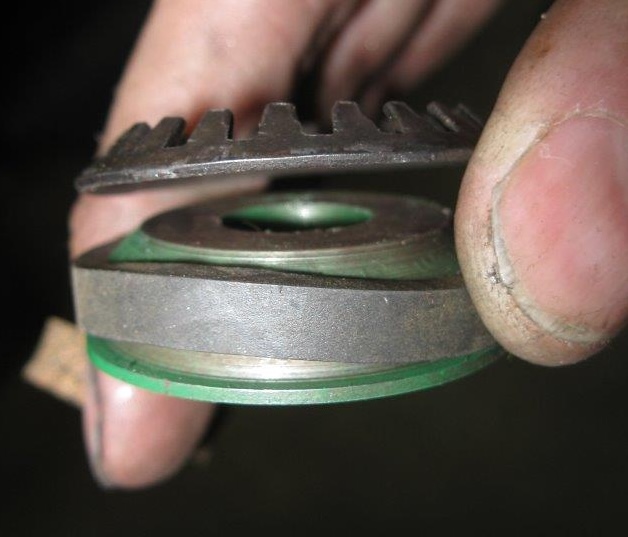
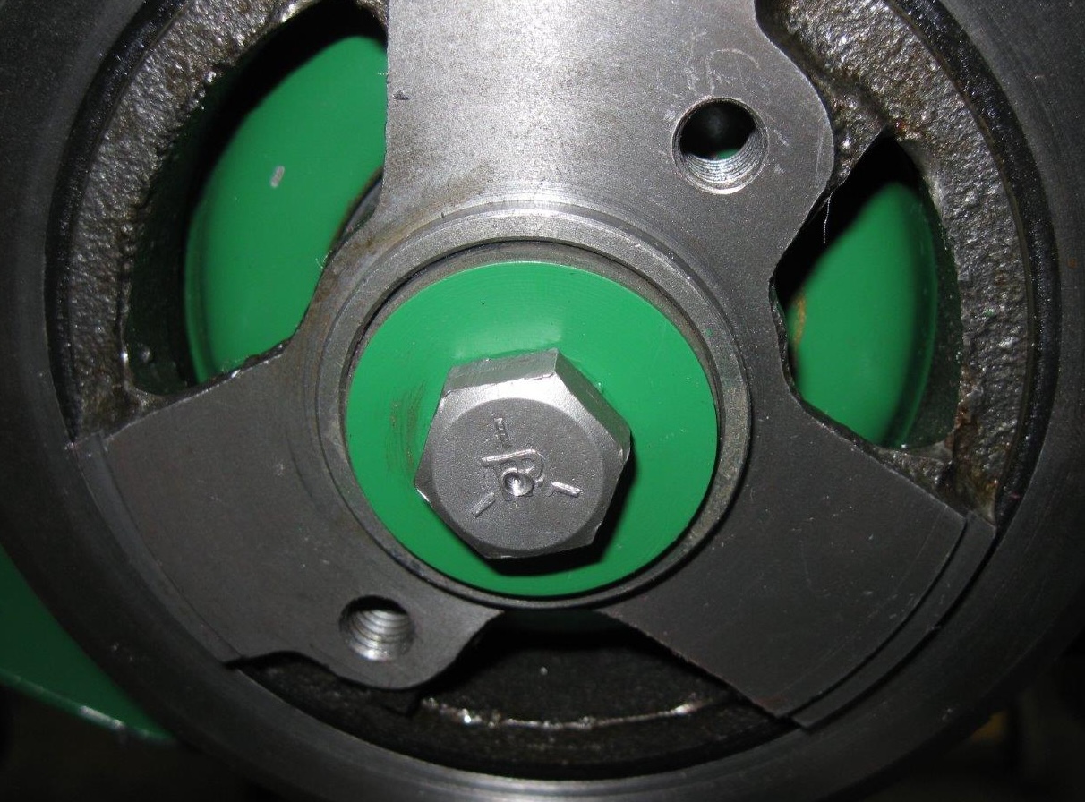
They’re an easy slip fit with a key, so you can’t go wrong installing it. But there is wet oil on the inside and so the weird and complicated seal is necessary else it will fling oil everywhere. It’s easy to do right. I add a wipe of Right Stuff for added insurance. Shown below is the correct sequence of parts from the service manual.
Engine Installation
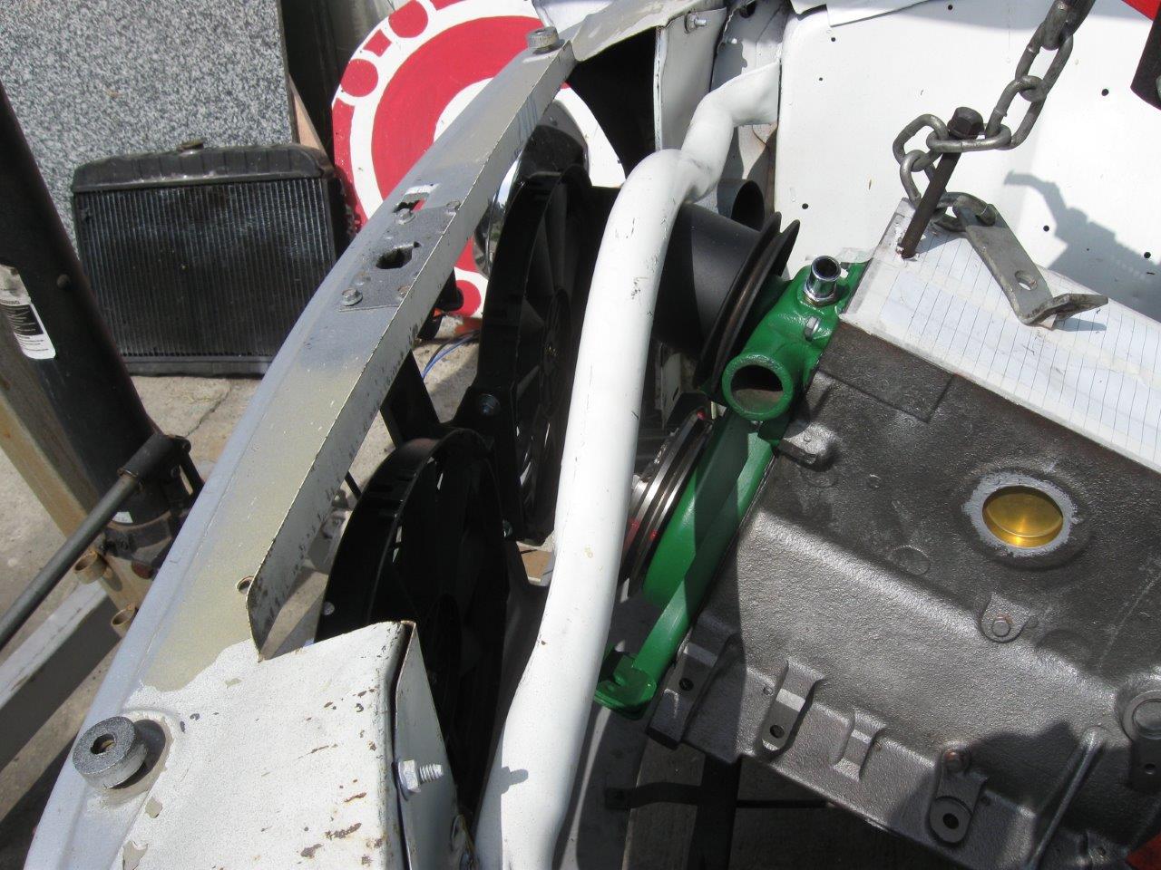
The engine and transmission was inserted as an assembly from below at the factory. Many Rambler Americans have had the front cross-brace cut out for this reason; it interferes with inserting the assembled engine from above. With it out of the way top-insertion is relatively easy, but you lose some body stiffness, especially if the modification was not done well enough to ensure that the brace does not move. This is an unnecessary modification. It’s much easier to remove and install the engine the way AMC (and earlier Nash… this is basically the same chassis as the 50-55 Nash Rambler) from the bottom.
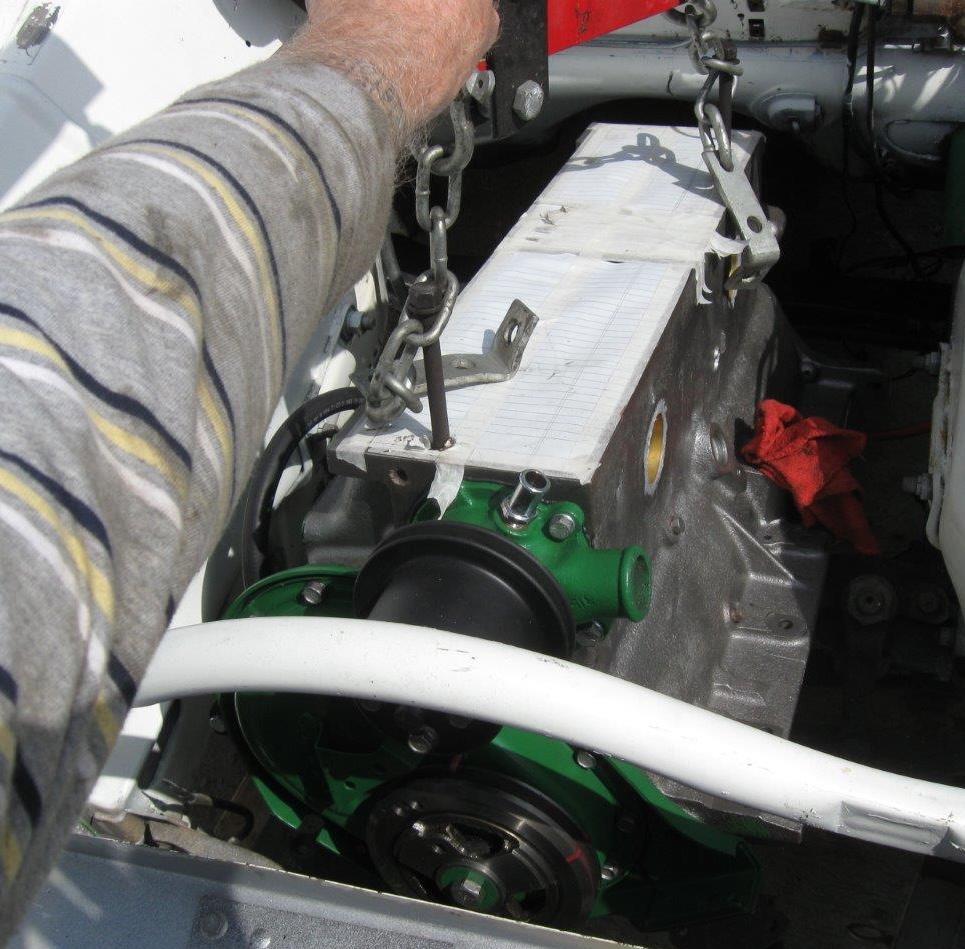
It’s not hard — remove the hood, drain and remove the radiator, attach engine hoist to engine, then take the bolts out of the front and rear crossmembers (crossmember to body) NOT the engine mounts! Lower to ground and detach hoist. It’s nice to have a furniture moving dolly to lower the engine on. Attach hoist to body via the crossmember mounting points or the bumper mounting points and lift body. It’s not that heavy without the engine and transmission, but the upper cross-brace WILL NOT support the weight of the body. Support the body with jack stands, move the hoist, and slide the engine out. Moving the body or engine is the hard part. A large furniture dolly under the engine or two smaller ones under the jack stands helps. If you have a lift it’s even easier — support the engine, unbolt the crossmembers, lift car. To install reverse the process. Frank’s done this many times — it’s actually much easier than trying to coax the engine and trans out from the top. If you’re rebuilding the engine taking the head off before removing the engine and installing after the engine is in makes it easier — the body doesn’t have to be lifted as high. At the least take the carburetor off first. Of course that’s not necessary with a lift.
Tom generally installs the block minus head, then puts the head on with the block in the car. He uses studs from ARP instead of factory head bolts. Besides more positive control over cylinder head torque they make excellent guides for the sticky gasket and cumbersome cylinder head. For information on studs see the Cylinder Head section.
Head gasket sealing is a serious problem with these engines and it takes a lot of care to get it right. The modern sandwich-type gaskets aren’t available, pretty much the one old style from Best Gaskets is it. This engine has less sealant than I use today. Fully coat both sides of the gasket and let it dry, drier than recommended. Also brush sealer around the problem areas on the left side (drivers-side) of the block, around the coolant passages. Indian Head Shellac Sealer (Permatex #20539, 2 oz. size) works well. So does spray on copper (Permatex #80697 or K&W #401612) sealer. Other spray sealers such as Permatex High-Tach should not be used on head gaskets due to heat and pressure.
Sliding the gasket and heavy head around on the block is always a problem, but the studs made this much simpler. Insert four (two would do) studs as guides for the gasket, then the head itself, which is best lowered by the crane due to weight. Even if you are using head bolts it’s advisable to have at least two longer guide studs (one near each end of the block) to help with head gasket placement. Just make sure they are long enough you can get them out after the head is in place. These can be hardware store threaded rod as long as they are being replaced by head bolts.
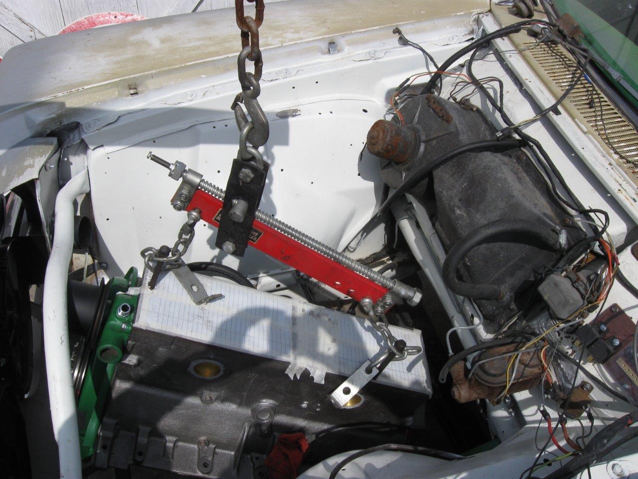
Use of a load leveler (red in the photos – about $50 at Harbor Freight – 2025) is highly recommended. Without it you will always be prying and pushing. With the leveler installation goes smoothly and easily, requiring many fine adjustments to height and tilt, but nothing gets bent or broken, no stressed parts. Tilt and adjust until it lines up and falls into place. It’s money well spent even for one use due to the time and effort it saves, especially if working alone.
Website contents, unless otherwise specified, © 2026 by Tom Jennings and Frank Swygert. Permission is granted for personal use with no remuneration. Corporations or any legal organization or their agents (employees or consultants or other relationships) expressly prohibited without written permission.