
Easy to construct and use wheel toe setting tool
by Tom Jennings, edited by Frank Swygert, 01-25-2026
I’m now doing my own front (and for the roadster, rear) suspension alignments, partly out of need and partly because I’m a cheapskate. Need, because even my local good tire shop uses a computer-driven alignment machine, and I get “its not inna computa” when I last asked for an alignment.
For caster and camber I bought the Longacre vial-type caster camber gauge (52-78260), slightly tedious because caster and camber interact, but ultimately easy enough and it’s nice to be able to spend the time to actually get it right, and know that it’s right.
For toe in I made this tool instead of buying. I also don’t like the design of many of the affordable ones (eg. toe plates). The tool I made aligns on the wheel, not the tire.
For clarity, this is what the toe tool sets. The drawing below is from this wikipedia article.
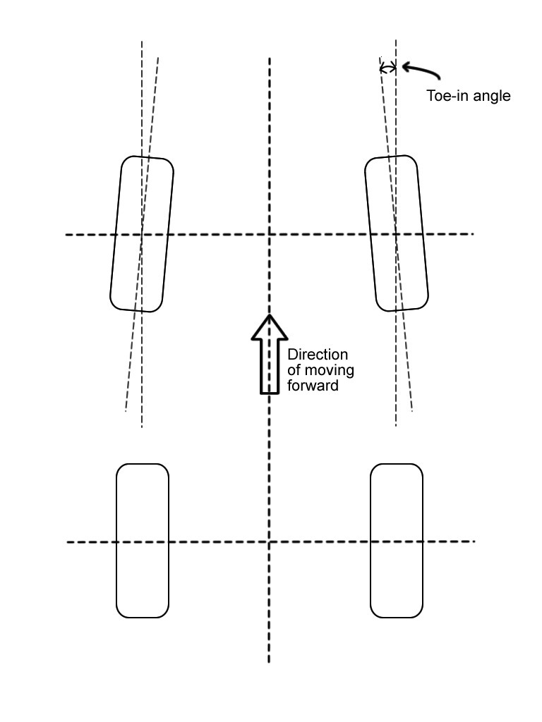
This tool is capable of excellent precision. On my roadster I run only 1/32″ of toe-in. I have tweaked it back and forth and with just over a year of hard driving on the tires (BF Goodrich Sport Comp-2) and 1/32″ is enough for the type of driving I did with that car. On my more sedate ’68 Rambler American I set toe-in to 1/16″. Factory specifications are 1/16″-3/16″, 1/8″ desired.
Construction
The tool is simply two lengths of one-inch square tubing welded into a reasonably-precise “T” shape, with three “probes”, small stands constructed from 1/4″ threaded rod or carriage bolts that contact the wheel rim. Two of these tools are needed, one for each side of the car. Many toe tools get all weird about mounting to the wheel. I use a simple bungee cord from fender lip to fender lip. This presses the tool onto the wheel adequately, and compensates for the wheel moving in the well.
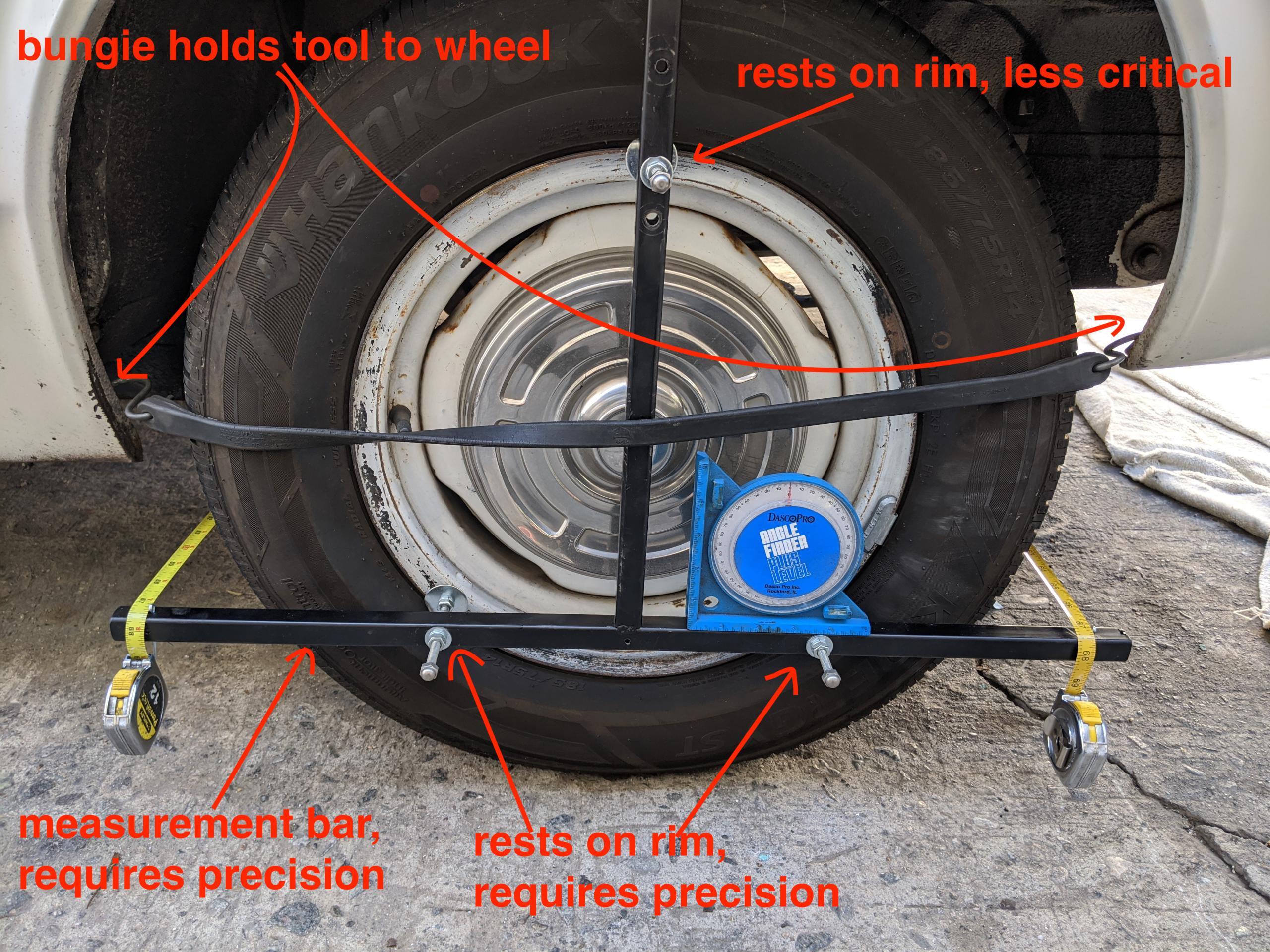
All measurement is done on the horizontal bar. The vertical is there to create a triangle to support the horizontal bar. In use the tool is adjusted with a level to be horizontal, so it should be flat in that plane.
Once welded into a “T”, find the center of the horizontal bar and mark it (scribe or center punch). I drilled a 1/8″ hole in mine. This should be the center of the vertical bar also. My two cars have 14″ and 16″ wheels. I worked out that two probes 10.5″ apart straddled the steel wheels just fine for both. (5.25″ from the center mark to the drilled hole for the 1/4-20 long bolt probes.)
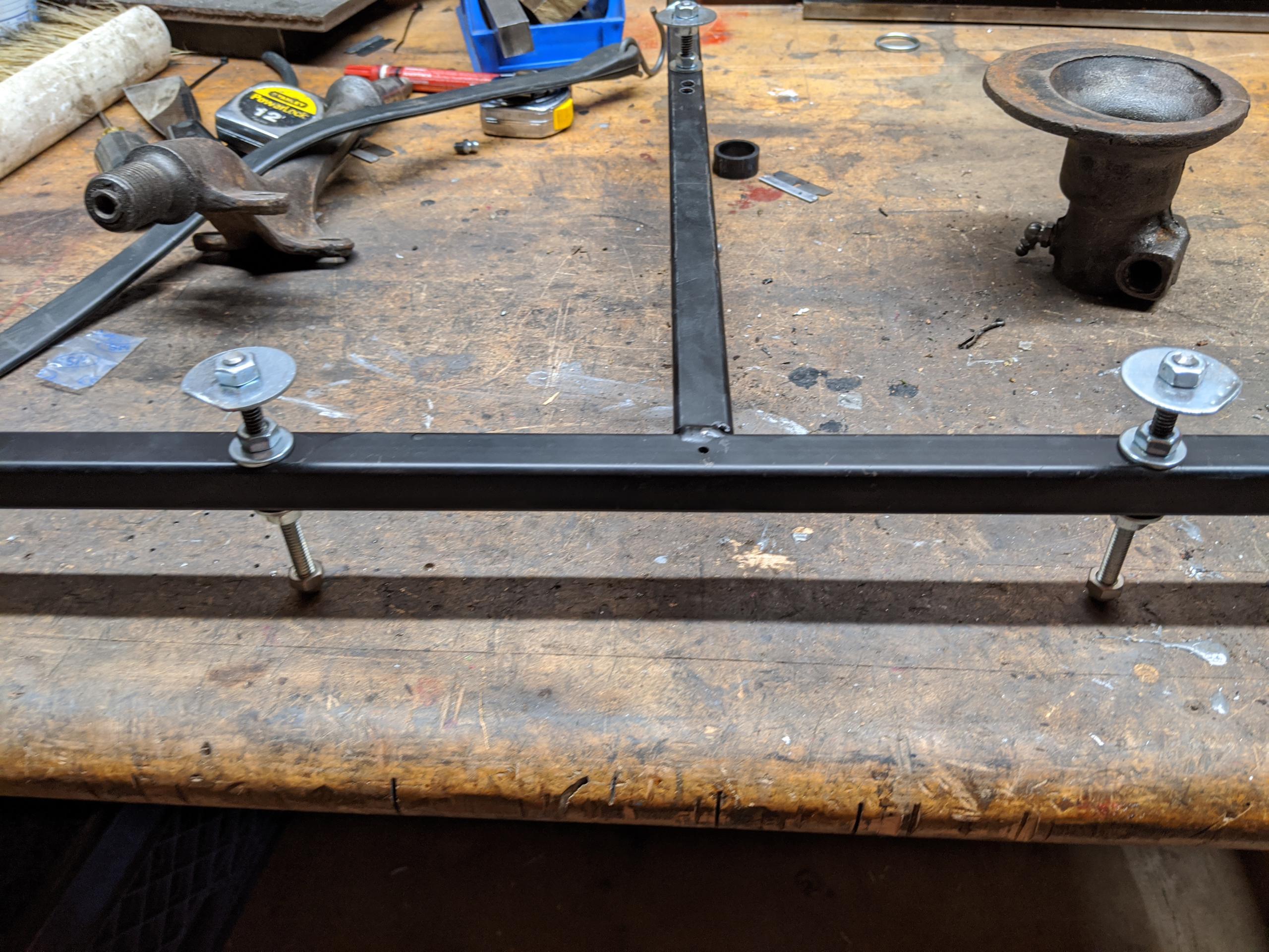
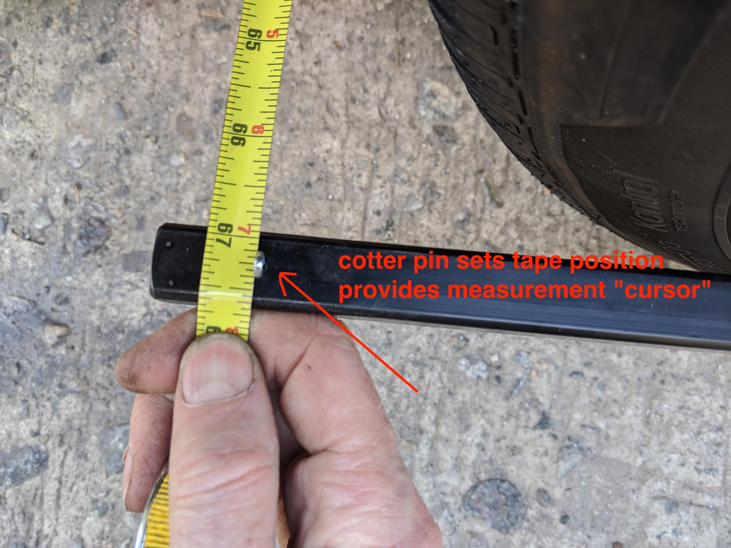
A hole is drilled in each “T” arm, 13″ from the center mark. A cotter pin is inserted in the hole as a guide for the tape measure. (The other two holes in the photo are a mistake.)
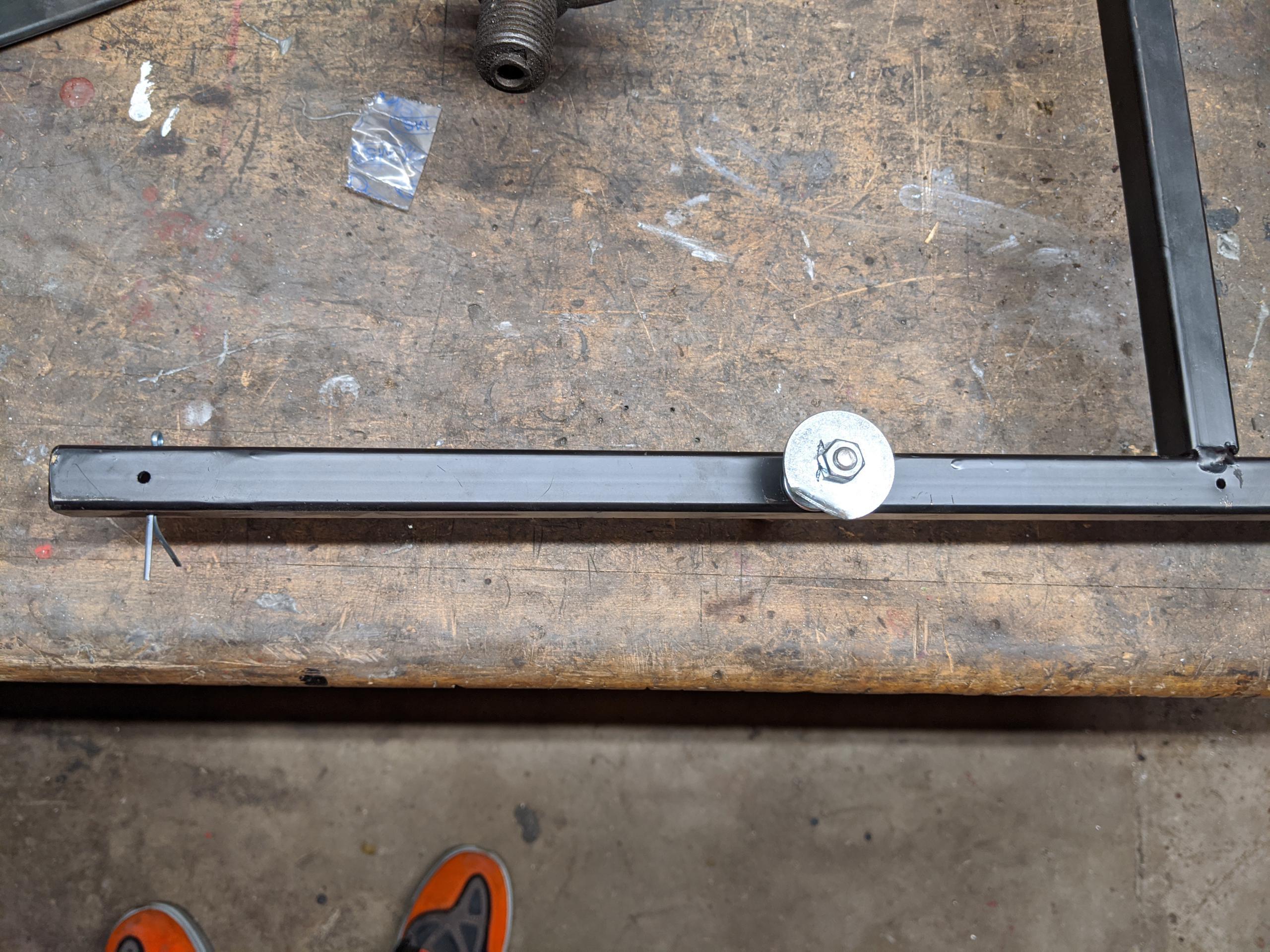
A third hole, and third probe, is installed in the vertical leg. This one does not need to be precise. I ended up drilling a number of holes, sort of experimentally, so that the top probe contacted the rim. In use, the tool more or less sits on the rim, held in place with the bungee.
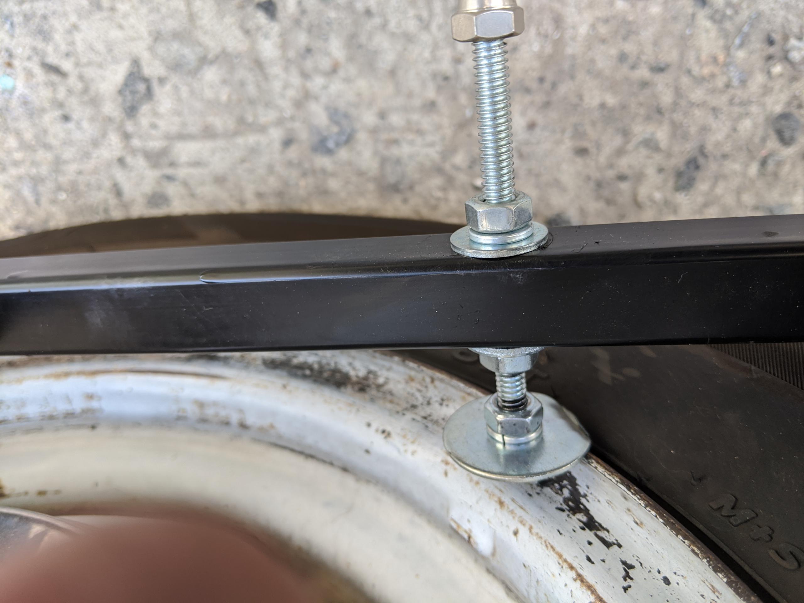
The probes are long carriage bolts with the heads chopped off. I had them in my junk box; threaded rod is fine. I used a fender washer as rim contact, with a nipped/bent corner to help locate the tool on the rim. A pair of nuts and a lock washer, tight, hold the washer in place. Another pair of nuts, washers, lock washer affix the probe to the “T”. Put the lock washer on top.
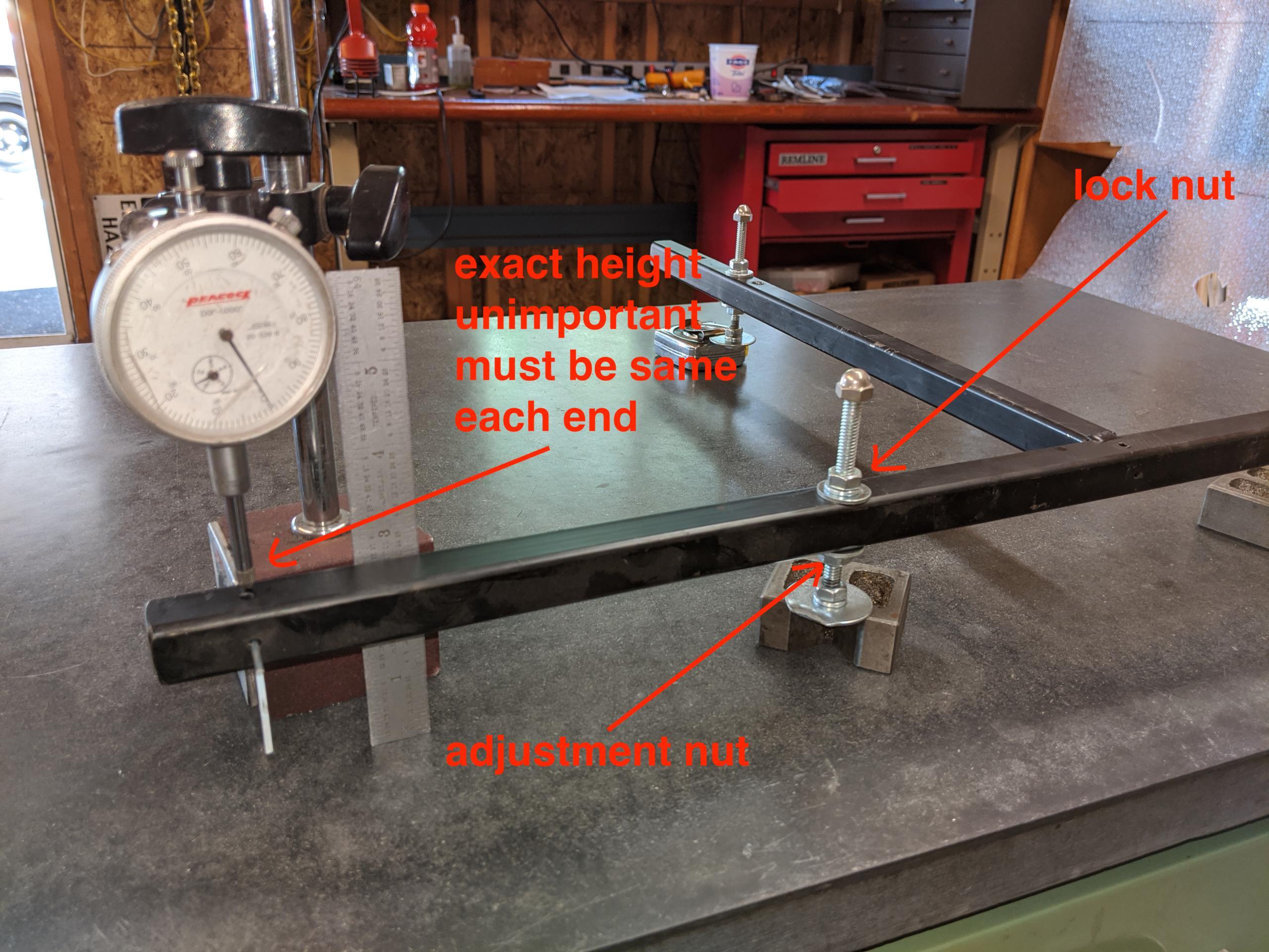
Before use the tool must be calibrated on a flat hard bench. A dial indicator or a precision steel rule or square is needed. Set all three probes to be about 3″ high. Place the tool on a hard FLAT surface. I have a black concrete laboratory table that’s pretty flat. I used some “V” blocks to support the bent fender washers off the table, some piece of junk to prop up the vertical’s probe at the same height.
The height of the probes on the horizontal bar need to be exactly the same height, as close as possible, preferably within a few thousandths of an inch. Any error here is multiplied when used on the car and you will transfer that error into your suspension. The vertical bar does not require accuracy, a tape measure will do.
Tweak the height of one of the probes so that the horizontal bar is exactly parallel to your flat surface. This sets the precision of your tool and the precision of your toe-in measurements. I used a steel rule to get it to one sixteenth, then the dial indicator to get it to about 10 thousandths.
Here’s my adjustment process:
- Tighten one side, use it as the “reference” height.
- Leave the other side loose. Nut and plain washer on under side.
From here you do the following until you are “close enough” to zero error:
- At the reference end, zero the dial indicator, or precisely measure the height
off the table. - At the adjustment end, read dial indicator/ruler while you adjust
height to half the height error (difference). - Repeat until error zero or tiny.
Tighten the top, lock nut and it’s done. Both tools must be calibrated this way.
That vertical probe…
The probe on the vertical bar is not critical at all. It only serves to ensure that the tool forms a triangle on the wheel. Tilt towards or away from the wheel is unimportant, because you will be measuring only perpendicular from the horizontal lower bar.
Tool in use
Aligning the steering box before you start
The first thing to do is to turn the steering wheel so that the steering box is precisely in the center of it’s travel. This is required no matter how you set toe in, it’s not peculiar to this tool.
There are various ways to determine this. One is to jack the wheels off the ground, turn the steering wheel to the left stop, then the right stop, and count the number of turns including fraction of a turn, then turn the steering wheel to the exact center.
Do NOT assume that the steering wheel will be centered. The reference is the steering box, not the wheel. If it’s off a tiny bit (the third spoke is off one or two inches) you can tweak it into place with the adjuster sleeves on the tie rods. If it’s off too much you must pull the wheel and re-position it.
The steering box internally favors the center position; centered has different characteristics than the gear teeth off to each side.
The pitman arm will probably be pointing exactly straight ahead. It’s useful to put paint marks on the pitman shaft and steering box to record where centered is. (My rebuilt Lares box came with yellow paint markings, very handy.)
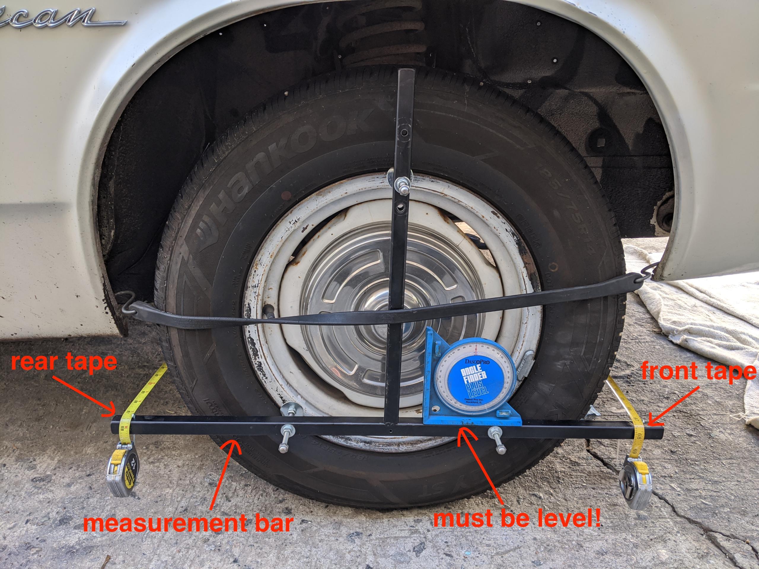
Using the toe tool
Place the tool onto the steel wheel, the “T” upside down, the probes of the bar sitting on the steel wheel above the lip, and hold in place with a bungee hooked into the lip of the fender fore and aft. If one is loose pull it outward (like a bow) and put some object between the bungee and the vertical bar.
Once it’s held in place, make each horizontal bar exactly level using a good bubble level or angle finder. When both are level with the earth, the two tools’ horizontal bars are exactly parallel in both planes, except for the toe-in (or out) error.
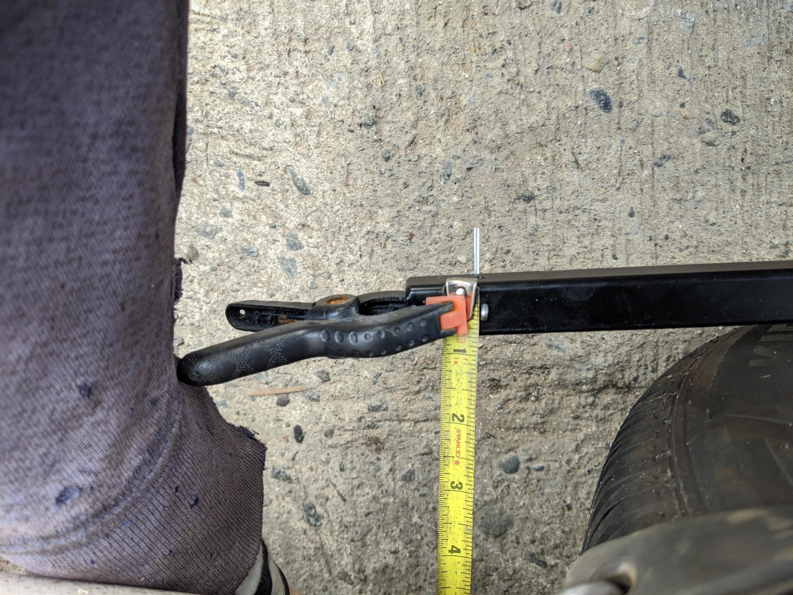
Two tape measures are required. At the “far” tool, place the tape end against the cotter pin/guide, and clamp there as shown. At the “near” tool, pull the tape taut and measure to the center of the cotter pin. The toe is the difference between the two tapes.
For 1/16th-inch of toe-in, you want the front tape measure to read 1/16th inch less than the rear tape.
You should be able to pull the tape fairly snug without either tool shifting. If it does, you will feel it. Fiddle with the bungees if this
happens.
Additional hint on setting toe
After setting toe in, you must roll or drive the car and check it again, especially if you’ve made more than a small (1/16″ or so) change to toe. The tires grip the (driveway) surface and deform, and the various moving parts of the suspension adjust to the forces you’ve just added with the adjusting sleeve.
The “correct” way is to put the front wheels on turn plates, so that tire grip is zero. Another trick is to sit in the driver’s seat, press the brake
pedal hard, and turn the wheels back and forth 10 degrees or so then recenter (trick stolen from Carroll Smith’s PREPARE TO WIN).
After aligning as per above, I take a test ride, pull back in without turning the wheel for the last few feet, and check it again. There’s often
small error found after driving the first time. Adjust and test drive again, then re-check. It may take a few times to get it right, but once you’ve done it a few times you’ll get better. Or just get some turn plates… (as little as $75 for a pair on Amazon, 1-25-2026)
Deprecated: File Theme without comments.php is deprecated since version 3.0.0 with no alternative available. Please include a comments.php template in your theme. in /home3/amcmagc1/public_html/wp-includes/functions.php on line 6170
Leave a Reply