
Rambler roadster T5 install
this is the final documentation for this install; it’s done and i’m
driving it now. the previous contents of this page, T5 install notes has notes and
data on paths not followed.
overview
this page documents the install of a Ford T5 transmission in a 1961 rambler
american chassis, attached to a rambler 195.6 OHV engine. the pre-1964 rambler
american chassis is a restyled nash rambler. in 1964 amc introduced an all-new
chassis for the “01 series” that was the platform for the later SC/Rambler and
AMX, then later Hornet, Gremlin, and the end of the line, Corcord. that chassis
is easy to work with, everything mostly bolts in. the earlier nash-based
chassis is completely different, and very very small.
this chassis had two transmission options: the Borg Warner M35 variant
automatic transmission and the T-96 3-speed manual transmission, with optional
overdrive. the rear axle was the small Dana axle, usually 3.31:1 ratio. the
driveshaft is a Nash-specific thing called by AMCers the “big nut” axle, due to
the bizzare and annoying rear spline coupler with a big pinch nut that
necessitates owning a pair of wrenches three feet long. the manual transmission
uses a typical removable bellhousing to which the two rear motor mounts are
also affixed. the transmission pattern is pure Nash. one other transmission is
known to fit in the hole: the AMC passenger car version of the T-14
transmission from the late 1960’s. it shares the same short clutch shaft and
small rectangular pattern. there are actually two variants of the transmission
pattern, on one, the lower two holes are higher about one inch. the T-14 is a
fine and solid transmission, but the gap between first and second ratios is
93%, which is pretty much like driving a four-speed but skipping second gear.
it’s terrible; i drove it this way for most of a year.
to make a long and already tedious story short, Modern Drive Lines makes an
adapter,
MD-401-2400S or MD-401-2400 that fits this Nash patterned bell
housing and accepts a modern T-5 transmission. what follows is how i installed
an MDL T5z transmission with this adapter, a narrowed 1998 Mustang 7.5″ axle,
and a nicely ordinary driveshaft. i ended up with four wheel disc brakes in
the deal.
these are the major issues and areas i had to deal with.
- there are two variants of the engine’s crankshaft, what AMCers call flat butt vs. volcano butt.
- clutch fitment is complicated by AMCs typical “parts bin” approach and today’s severe parts availability issues.
- fabricating new rear engine mount system to replace unavailable parts.
- clutch release fork (“throwout lever”) issues easily resolved.
- T5 transmission necessitates fairly severe floor pan clearancing.
- T5 transmission requires a “fifth engine mount”, since it otherwise dangles off the end of the bell housing.
- it is inconceivable to me that anyone would go through all this work
and even think about keeping the big nut axle, therefore rear axle swap
is assumed, either later model AMC or narrowed Mustang, etc.
each of these issues has a section below. most of the work was in research
and fitment, the work itself was fairly straightforward and has worked out
fine.
CRANKSHAFT
AMC (and Nash) delivered these engines with two different crankshaft flange
styles that AMCers call flat butt and volcano butt. there is no consensus or
documentation as to why one or the other was shipped. my engine has a flat butt
and factory T96 with overdrive, but many lore has it that manual transmission
cars must have a volcano butt for the pilot depth to be correct; my iron
disagrees. volcano vs. determines the location of the transmission’s input
shaft pilot bearing, longitudinally, with volcano butts pushing the pilot
bushing further to the rear of the car.
PILOT BUSHING FITMENT
flat butt cranks accept a sintered bronze pilot bushing that AMC continued
to use up through the 1980’s. the flat butt pilot bushing is 1.050″ OD, is
readily available in pretty much any inside diameter needed. on flat butt
engines the outer edge of the pilot bushing protrudes 0.5″ from the
engine/bellhousing mounting surface.
volcano butt cranks accept only one very small bronze pilot bushing, Dorman
690-004, which is .815″ OD for a .628″ ID. the shape of the volcano is such
that it cannot be bored out to accept a larger OD bushing, and the bronze
bushing itself is too thin to bore larger. on volcano butt engines the outer
edge of the pilot bushing protrudes 1.25″ from the engine/bellhousing mounting
surface.
the problem
the position of all the components in the “clutch stack” is critical. the
clutch stack consists of the longitudinal (car length-wise, front to rear)
position of all the critical components — engine, crankshaft butt,
bellhousing, flywheel face, clutch pressure plate fingers, release bearing,
release fork, and the penetration depth of the transmission input shaft splines
into the driven disc, and the length of the bearing retainer snout on which the
release bearing slides. all of this stuff is a huge PITA if you get any of it
wrong.
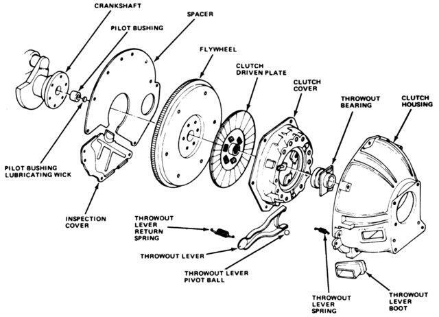
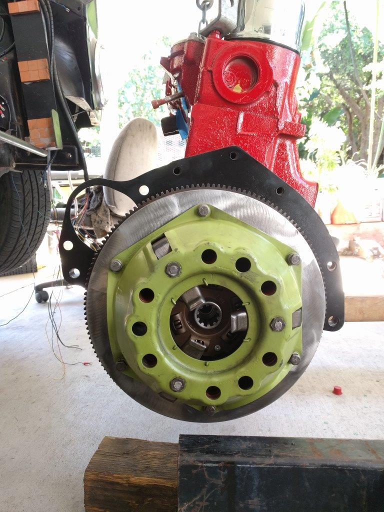
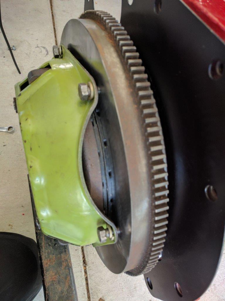
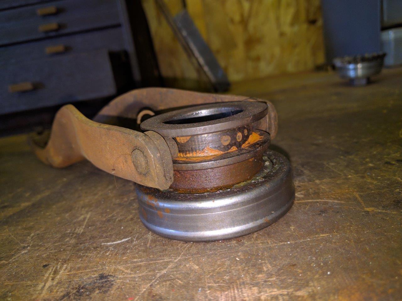
the pictures below shows the actual position of these components in the
clutch stack as assembled. i went through some effort to work this all out well
before i stuck anything under the car. i did not want to have to take it all
out and fix problems that i could have identified in the first place.
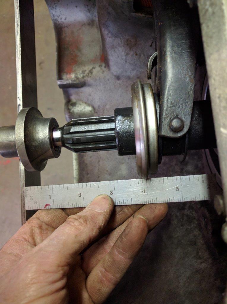
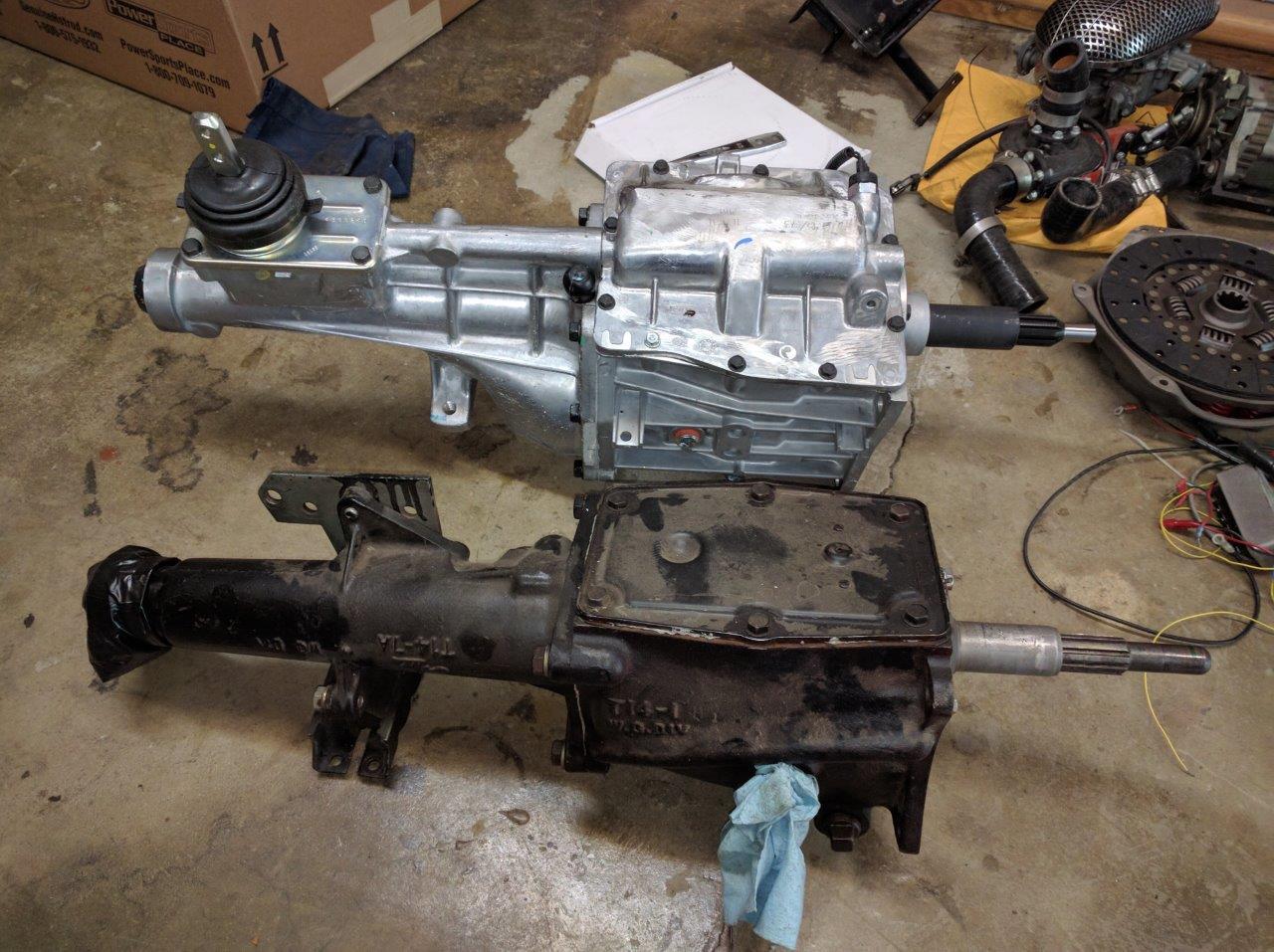
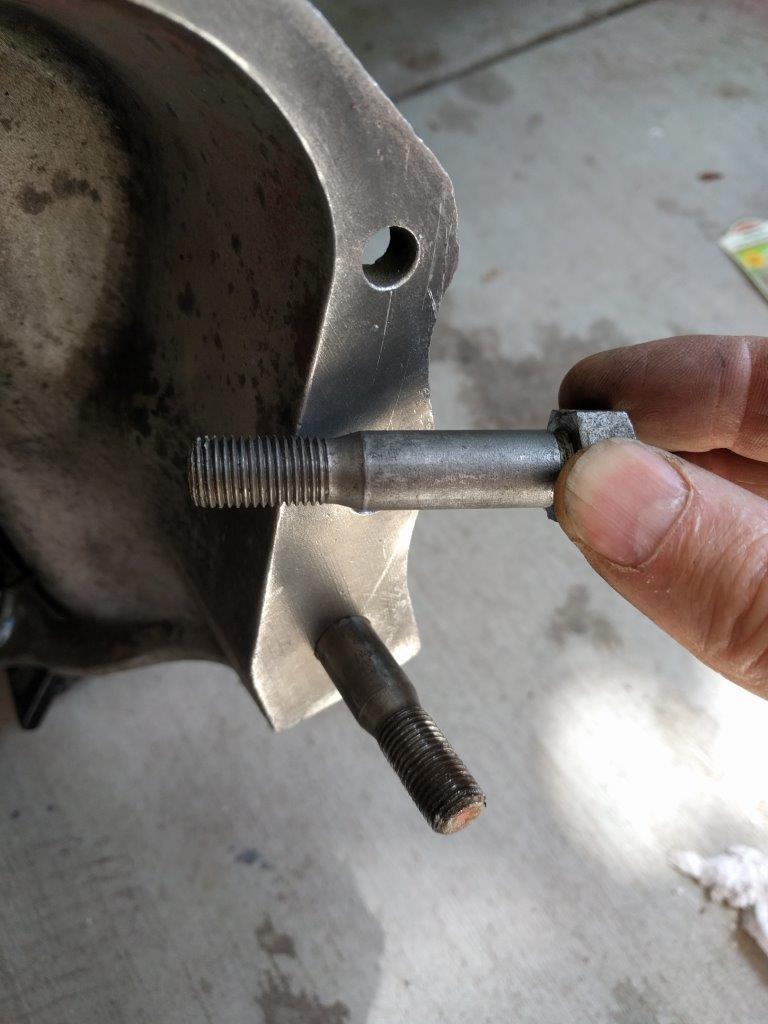
shown below in the top picture is the relative position of the T14’s input
shaft (the factory T96 is the same) to the engine/bellhousing mounting surface.
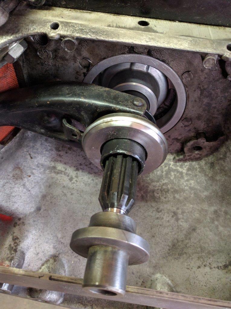
in the second picture note the substantial difference in input shaft length
between the T5 (top) and T14 (bottom).
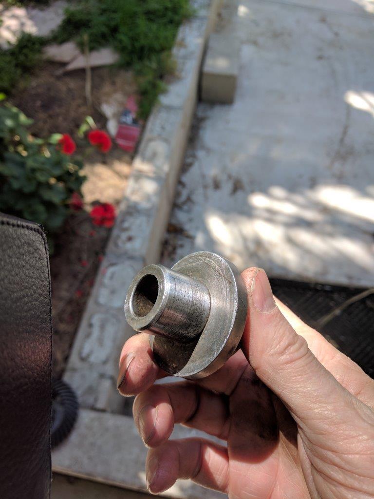
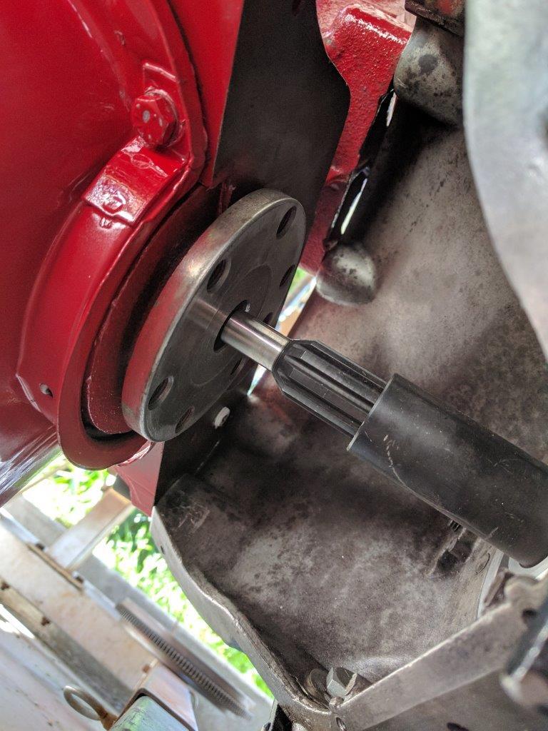
the solution
Galvin’s AMC Rambler parts sells
a volcano adapter that is a press fit into a flat butt crank and turns it into
a volcano butt. the issue with the small diameter pilot tip was resolved by
having Modern Drivelines reduce the transmission input shaft pilot tip diameter
to .625″. it is probably possible to find or build a T5 transmission with one
of the longer imput shafts but then you must make sure that the rest of the
clutch stack dimensions are correct, and they are critical. machining the input
shaft incurred a one time cost that allows use of off the shelf wear parts.
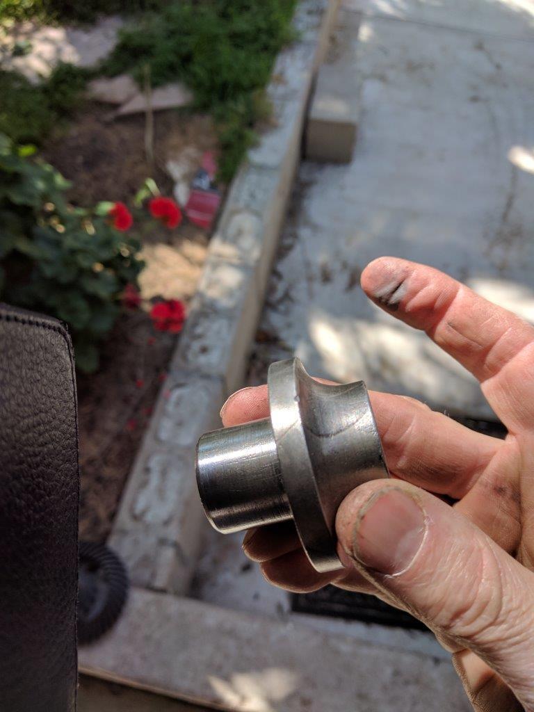
the adapter was a tight fit. i hand-sanded it smooth, gave the first 1/8″ or
so a faint taper on a belt sander, sanded the crank hole smooth, put the
adapter in the freezer for a couple hours, lightly oiled it and drove it into
place with a hammer and block of wood.
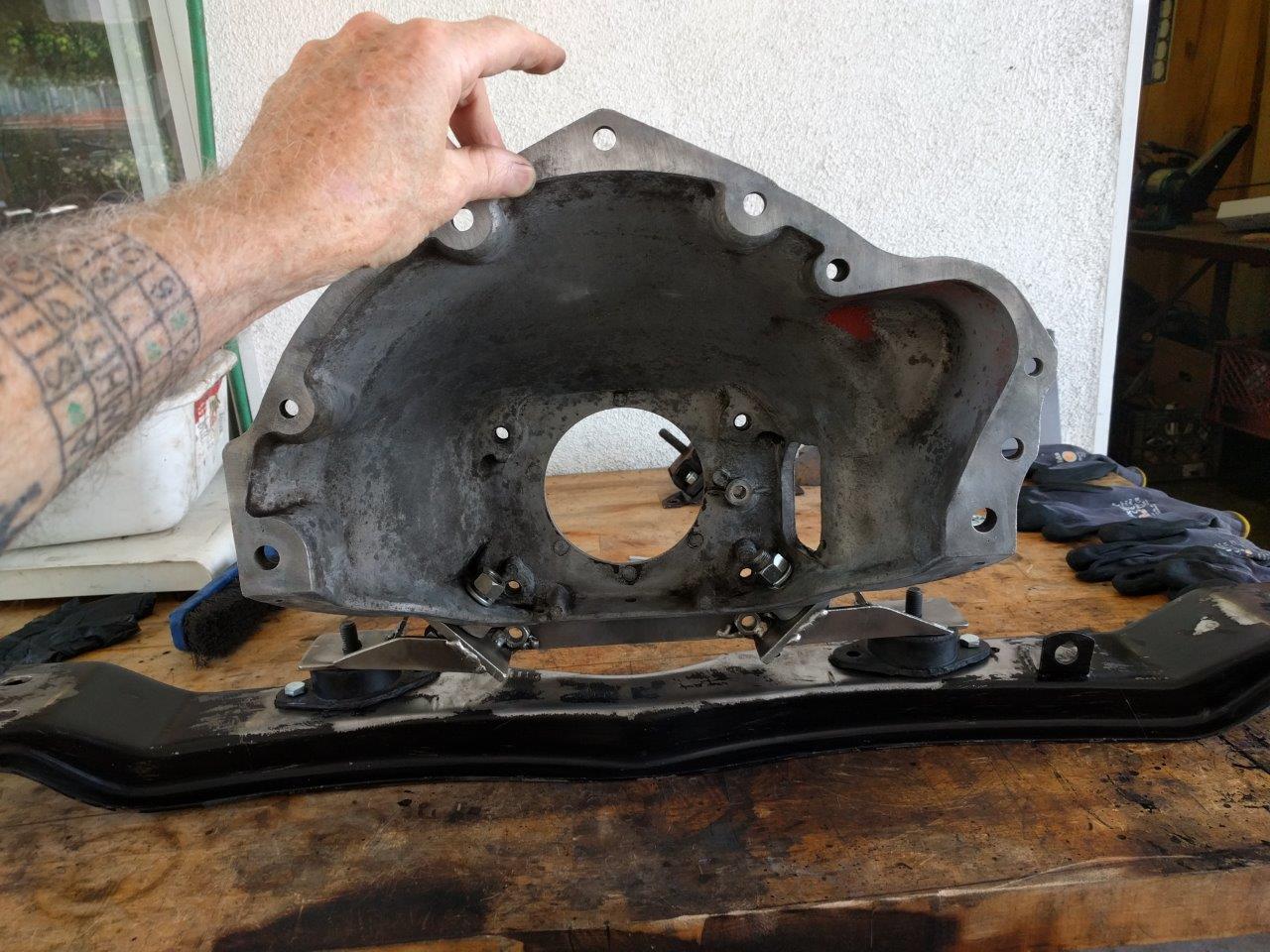
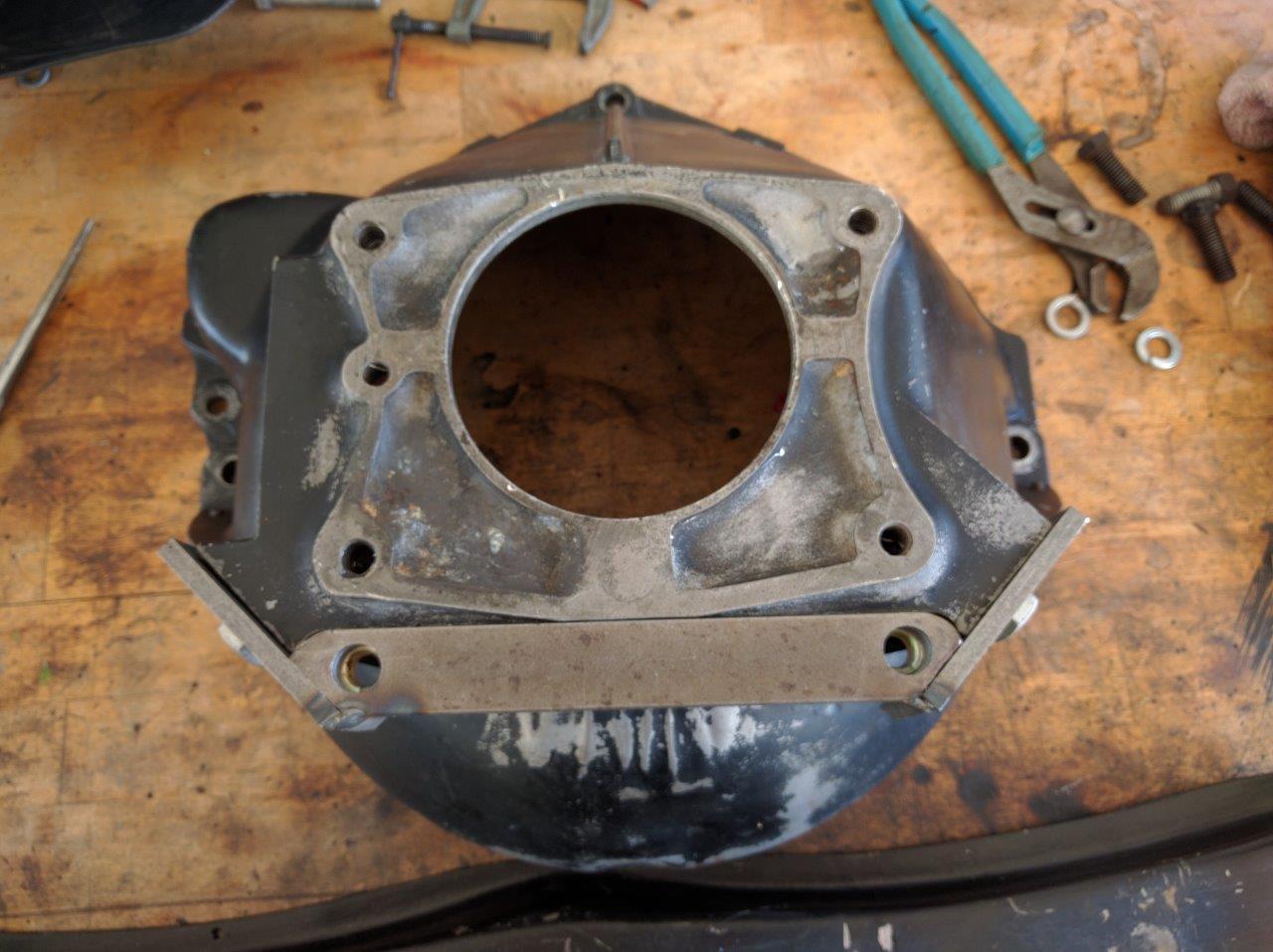
BELL HOUSING
as far as i know no one has ever tabulated nor compared or even measured 01
series bell housings. time to start, see below. if you care to contribute, i’d
appreciate it. of major importance is the overall depth, face to face. the part
number can be found inside the bell, just below the throwout fork pivot, cast
into the bell. you might have to wire-brush the gunk off to see it.
in the 01 series chassis the bell housing also supports the rear motor
mounts; there is no “transmission crossmember” nor true transmission mount in
this chassis. like an old Y-block Ford car the transmission dangles in free air
off the back of the bell. without reengineering the chassis for a rear
transmission crossmember and mount (which honestly wouldn’t be that hard to do)
you are stuck with this odd, tiny little bell that fits in the hole,
accommodates only the small 12″ flywheel setup and has only one (1) manual
transmission option: the Borg Warner T96. you have not heard of that
transmission before for good reason. it sucks.
i suspect that there may exist different-depth bellhousings though i find no
evidence of them in the factory parts catalog i have (1963). given that there
is not one documented instance of a T96 transmission clutch shaft other than
the standard 7″, and that both flat and volcano cranks indeed have manual
transmissions behind them, the difference must be in the bell housing. another,
maybe more likely possibility is that AMC juggled things so that if a car
needed a manual transmission, they always used a volcano butt crank. both seem
to have existed at the same time.
01 series bells are easy to identify; they have bosses for motor mounts at
about 4 o’clock and 7 o’clock, and a stamped removable cover below (necessary
to gain access to the motor mount bolts). it’s also very small.
Rambler early six bell housing dimensions
| part number | depth | application notes |
| 3145345 X3 | 6.625 (6-5/8″) | T96, flat butt crank |
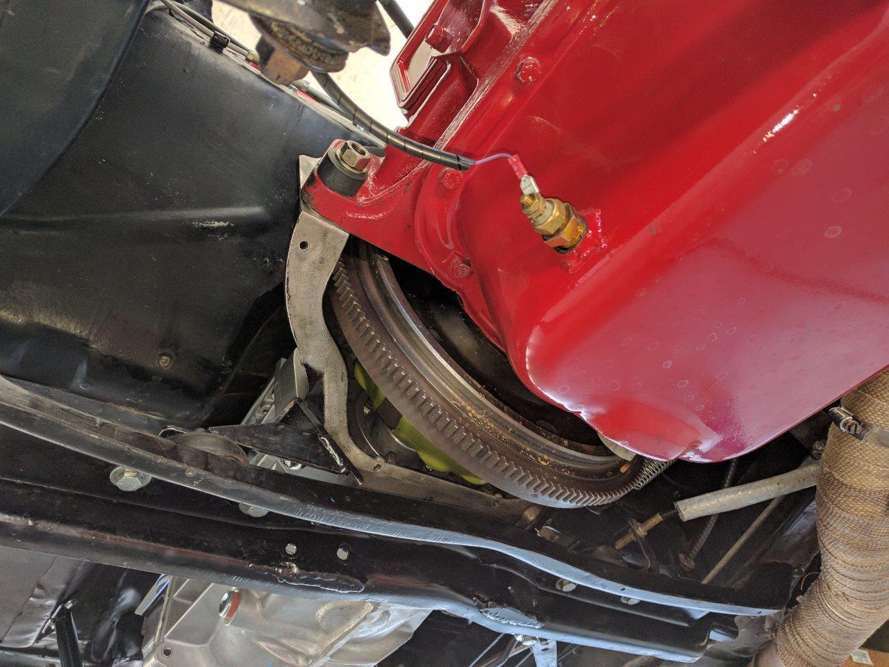
the problem
the bellhousing bolts to the engine block casting with special
close-tolerance dowel bolts and not separate dowels, meaning that if the
transmission input shaft is not precisely centered on the crankshaft
(doubtful), you cannot buy or easily make offset dowels to fix any
misalignment.
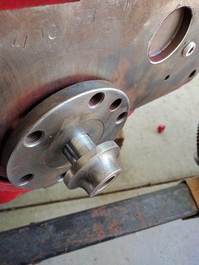
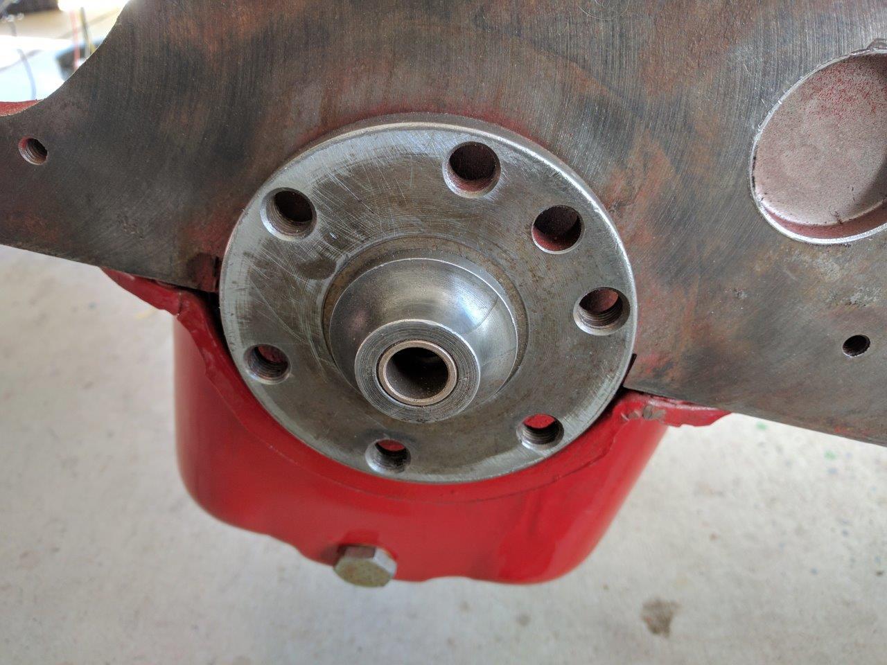
i fixed the misalignment error by adjusting the position of the MDL adapter
on the bell. i used the usual method to measure the error (dial indicator on
the crankshaft indicates the error as the crank is rotated, as shown below)
then “moved the holes” on the countersunk bolt holes by counterboring the holes
offset to one side and cutting them slightly (.010″) deeper. it took two passes
to get error under .002″. i did the drilling on a Jet mill-drill with a vernier
table; initially centering the countersink in the exiting hole, lifting it up,
cranking the table to one side, then counterboring down at the new
location.
(yes, the dial indicator face is pointing inwards; the bellhousing has a
removable bottom and i had to lay on the ground to look up into it.)
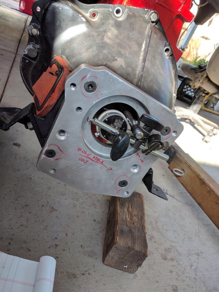
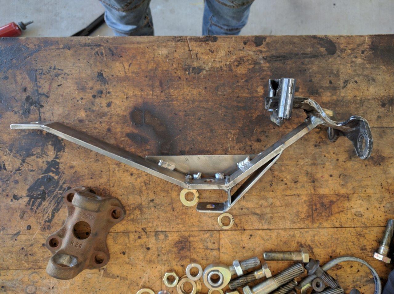
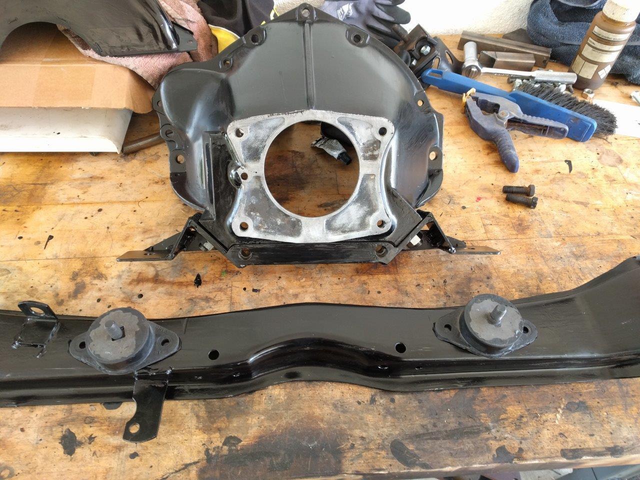
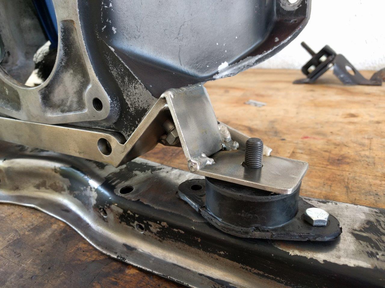
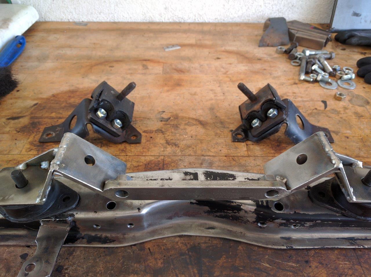
MODERN DRIVELINES ADAPTER TO BELL HOUSING
it does indeed just bolt on and work. however my bell has the funny bolt
pattern where the two lower holes don’t match. the rear motor mounts are no
longer available. i made this adapter that solved both problems at once — a
saddle that replaces the unobtainable isolators with the very common front
isolators and adds the lowered bolt holes.
![]()
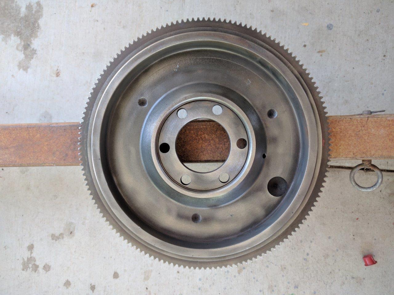
FLYWHEEL AND CLUTCH
flywheels for this engine interchange with early 199 and 232 engines. the
195.6 and some 199/232 flywheels are just over 12″ diameter at the ring gear
teeth. some 199/232 flywheels are approximately 14″ diameter and while they
will bolt onto the crankshaft, they won’t fit inside the bell housing.
these flywheels will be drilled for either 8″ or 9″ clutches, or they may be
dual-drilled.
the problem
both size AMC clutches are becoming very scarce, with the smaller one
extremely difficult to find. available at this point are rebuilds, only, and
especially difficult are driven discs, but we don’t care about those because
they don’t fit the T5 transmission. the AMC clutch driven disc, either 8″ or
9″, has a 1″ x 10 spline hole, the T-5 requires a 1-1/16″ x 10 spline hole.
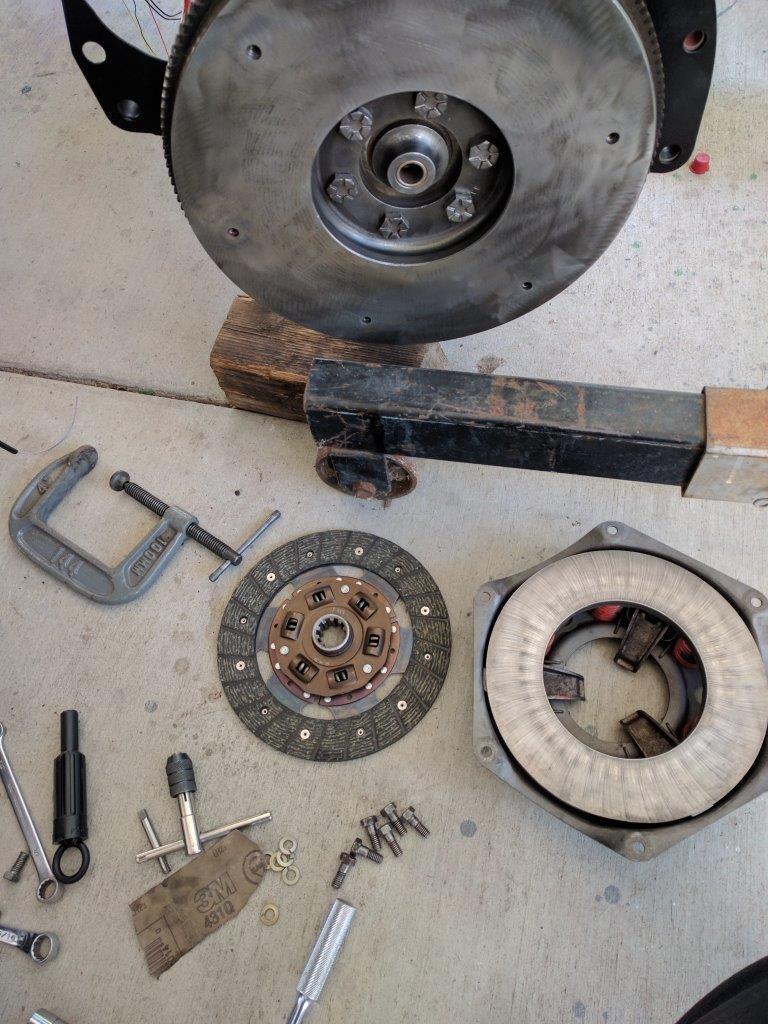
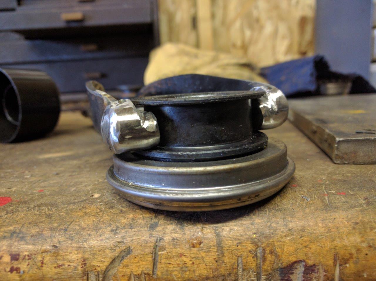
the solution
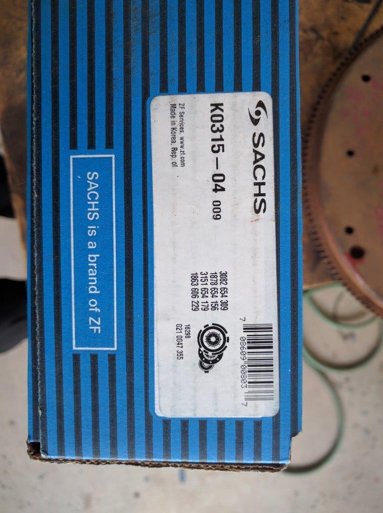
a clutch kit for a 1993 Ford Mustang 2.3L four cylinder car has the parts
you need (Sachs K0315-04). the Ford driven disc will fit under either the AMC
8″ or 9″ pressure plate (picture directly above). the Ford pressure plate very
nearly bolts on; other than the bolt pattern the Ford pressure plate fits and
the finger height above the flywheel is correct. you will obviously need to
have the flywheel drilled, and very accurately. i was lucky enough to have two
complete AMC 8″ clutch setups (one in car, one spare) or i would have done
this. the cost of Ford parts now (2016) is such that the entire Ford clutch
kit, pressure plate, driven disc, throwout bearing, alignment tool, and lube,
all new, cost less than one rebuilt used AMC part.
TRANSMISSION BEARING RETAINER NOSE, RELEASE BEARING, CLUTCH DISC
in many T5 retrofits the bearing retainer snout, on which the release
bearing rides, ends up being too long, interfering with the pressure plate’s
release fingers. i did not have this problem, because the MDL adapter’s 1″
thickness pushes the transmission back that amount, neatly eliminating this
problem.
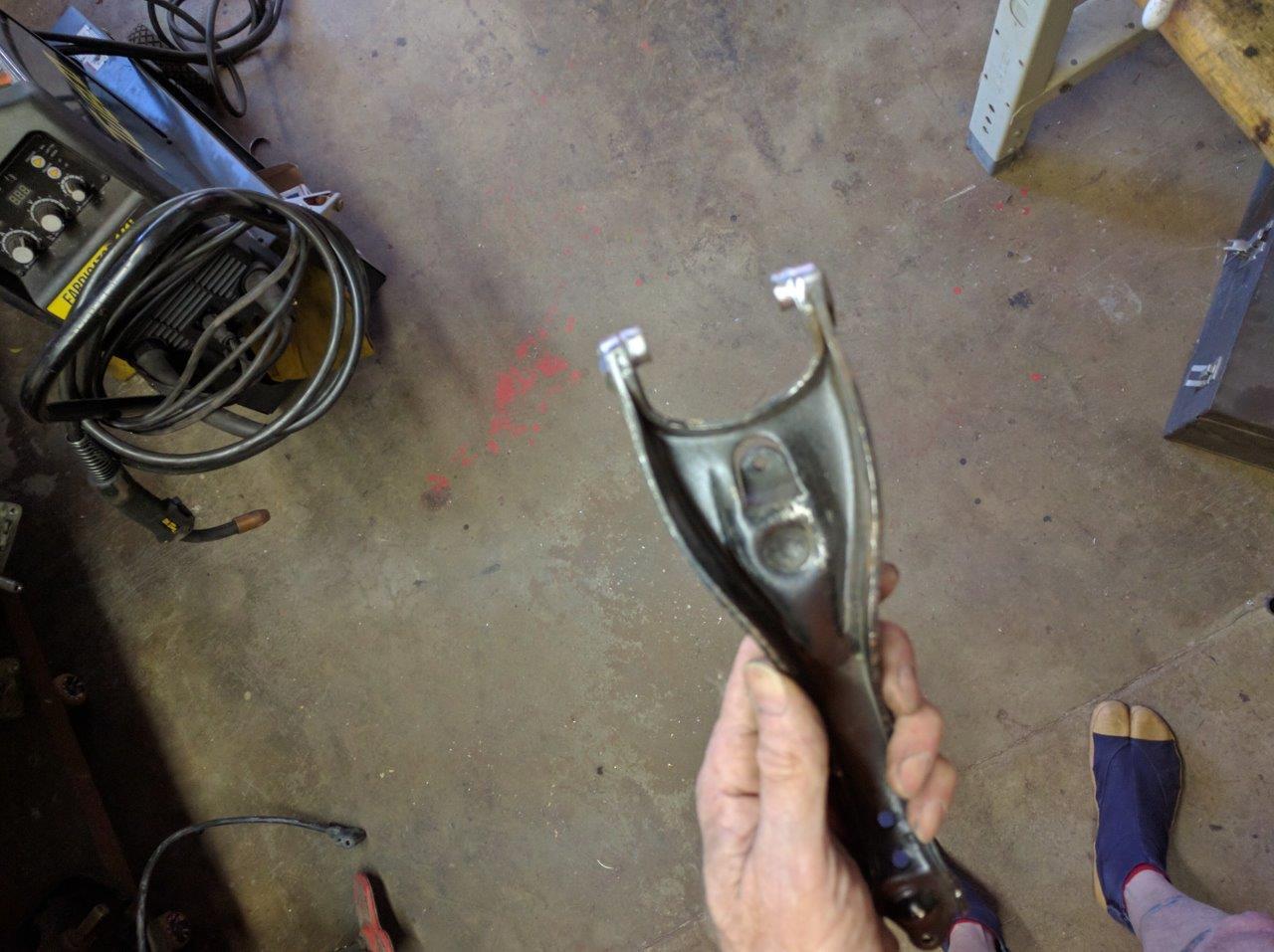
CLUTCH RELEASE FORK (aka THROWOUT LEVER)
the problem
the AMC clutch release bearing won’t fit the T5 bearing retainer nose, and
the AMC clutch fork won’t fit in the T5 release bearing’s groove.
the solution
there are probably many solutions including a retrofit hydraulic clutch. i
simply modified the fork to fit the T5 release bearing, which has a nearly
identical contact pattern on the clutch pressure plate fingers. i’m using a T5
bearing on an ancient 8″ Rambler clutch.
a secondary issue is in the stack height: relative to the flywheel surface,
the release bearing groove is closer on the T5 setup than the old AMC setup.
this has the net effect of the pushrod socket end of the lever in a “clutch
pedal depressed” position, eg. more towards the back of the car. the simple
solution is to shim the fork pivot. given the amount of leverage, a single
split-lock washer provided adequate clutch release. it would have been better
to use two, or make a real spacer, but given the generous remaining threads and
the nature of the load on it, two washers would be a fine solution.
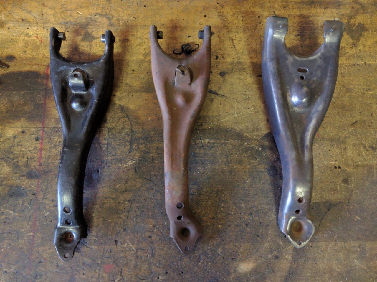
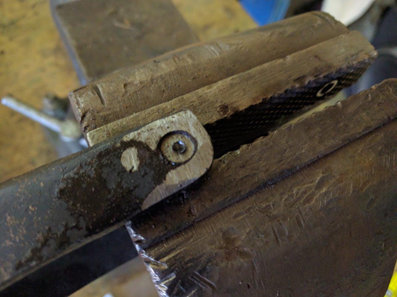
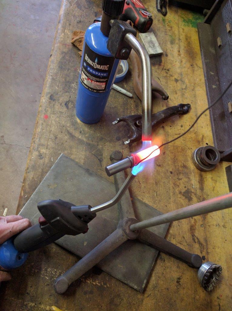
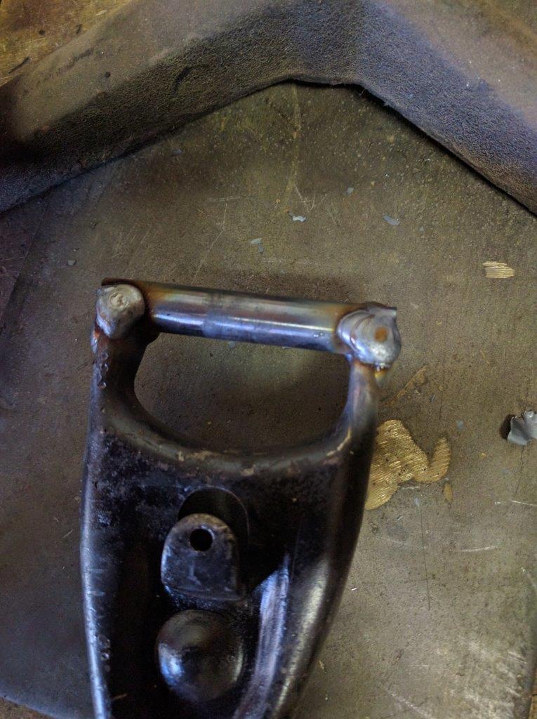
the modification to the fork was to cut out the two small AMC fork tips,
notch the stamped fork so that a length of 1/2″ drill rod laid neatly across
it. the rod was annealed first (it’s crazy brittle) then welded in place. the
unwanted center chunk of the rod was cut otu with a hacksaw. this method keeps
the two new tips exactly parallel and made it much easier to hold in alignment
to weld (as opposed to trying to keep two short nubs in the proper place).
there may be a stock fork and/or a different release bearing combination
that solves the problem more directly. i had a few different types in my
junkbox but none were suitable.
REAR ENGINE MOUNT
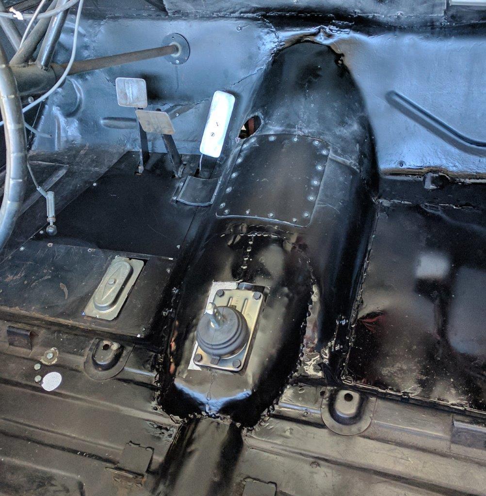
TRANSMISSION CHASSIS FITMENT
the problem
obviously, the problem is to make the T5 fit in the hole where the T96 was.
the Nash-based chassis cars like mine require additional work to make them
physically fit. that info is elsewhere.
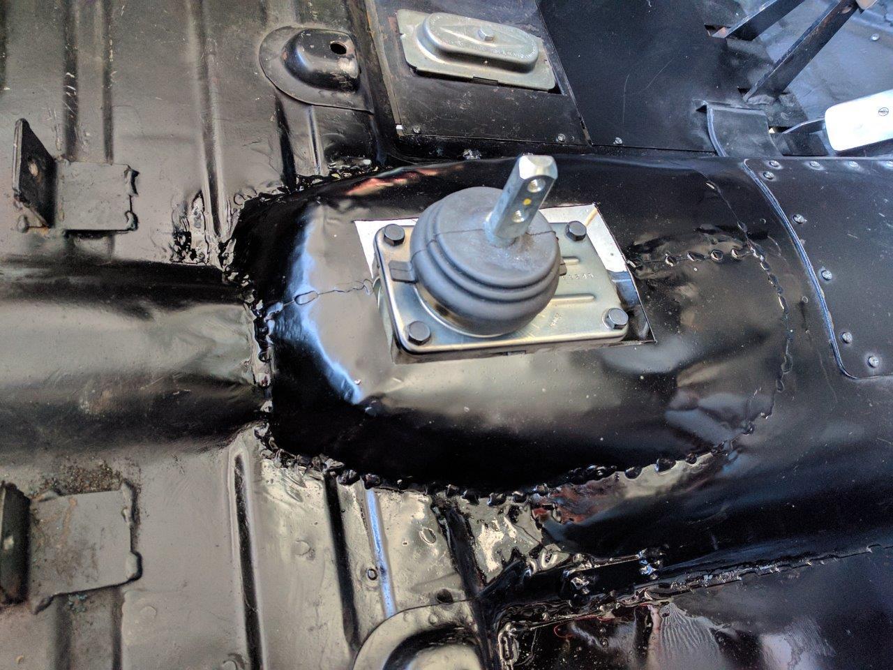
you are pretty much on your own here. my chassis is hardly typical, i turned
a ’61 Rambler American 220 sedan into a roadster, so YMMV. the rear portion of
the transmission hump is simply too small (the T96 and T14 have tailshaft where
the T5 has the shifter box protrusion) so i cut it out.
the “transmission crossmember” isn’t — it’s the rear motor crossmember, is
quite far forward. this is a unibody, and a true monocoque; there is no frame
whatsoever. the crossmember had to be notched and reinforced to clear the
larger T5 body.
on these chassis the transmission simply dangles off the back of the the
bellhousing; there is no rubber isolator/mount at the rear. this might have
been tolerable in the 1950’s, with low engine torque, low speeds, rough roads,
and low expectations. but even stock the transmission yoke end lifts and arcs
up in the direction of engine rotation, causing U-joint misalignment and
vibration at the moment of accelleration, after which it falls back into
place.
with twice rated horsepower, a real transmission capable of applying actual
torque to the driveshaft, in a previous incarnation of this car (with T14
transmission and original “big nut” axle) i could easily grind the front yoke
and U-joint up against the driveshaft tunnel. i have shiny spots to prove it.
this is with all good and solid parts.
the short of it is, you need to install a “5th motor mount” to snub this
transmission yoke torque rotation. it is important to note that if the rear
output shaft is held concentric with the driveline center, the torque on that
5th mount will be near zero — it doesn’t take much to hold it in place. but
once it gets an offset angle, the torque increases non-linearly.
i dealt with this in my rigid wishbone suspension covered elsewhere on this
site.
![]()
![]()
![]()
![]()
![]()
![]()
![]()
![]()
Deprecated: File Theme without comments.php is deprecated since version 3.0.0 with no alternative available. Please include a comments.php template in your theme. in /home3/amcmagc1/public_html/wp-includes/functions.php on line 6170
Leave a Reply