
Early American “big nut” axle
11-10-2025 Edited by Frank Swygert. Written by Tom Jennings
Just removing the engine, transmission or driveshaft? You DO NOT have to remove the “big nut” yoke! See “The Easy Way” at the bottom of this page… (that section written by Frank Swygert)
Even amongst AMCers there’s a lot of rumor and fear about the driveshaft system on these early Americans, known as the “big nut” axle. “Modern” American cars have the rear U-joint yoke fixed to the rear axle pinion shaft; the big-nut rears instead have a splined slip joint with a compression sleeve tightened with a … big nut, tightened to 300 foot-pounds. With big wrenches.
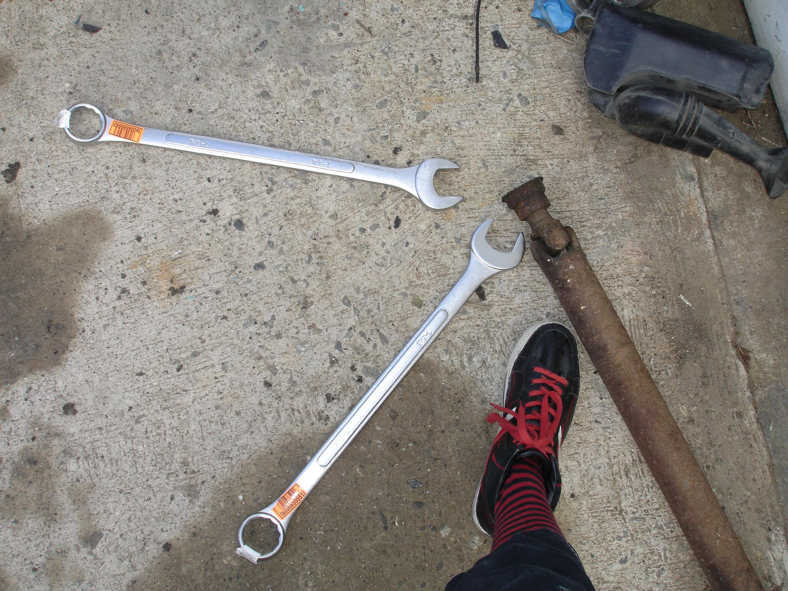
I was warned of the horrors of working on this thing, but it simply wasn’t that bad. I bought a pair of 1-3/4″ combo wrenches, Fuller brand, total cost for two including shipping: $50 (in 2009).
It did require different procedures but none of them were particularly difficult.
Since apparently few people have seen these things I took some photos of the procedure to debunk the mystery. Many photos below.
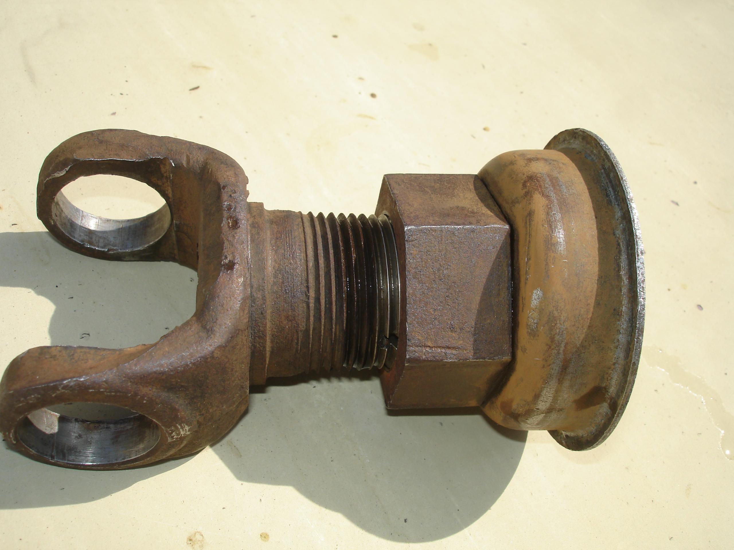
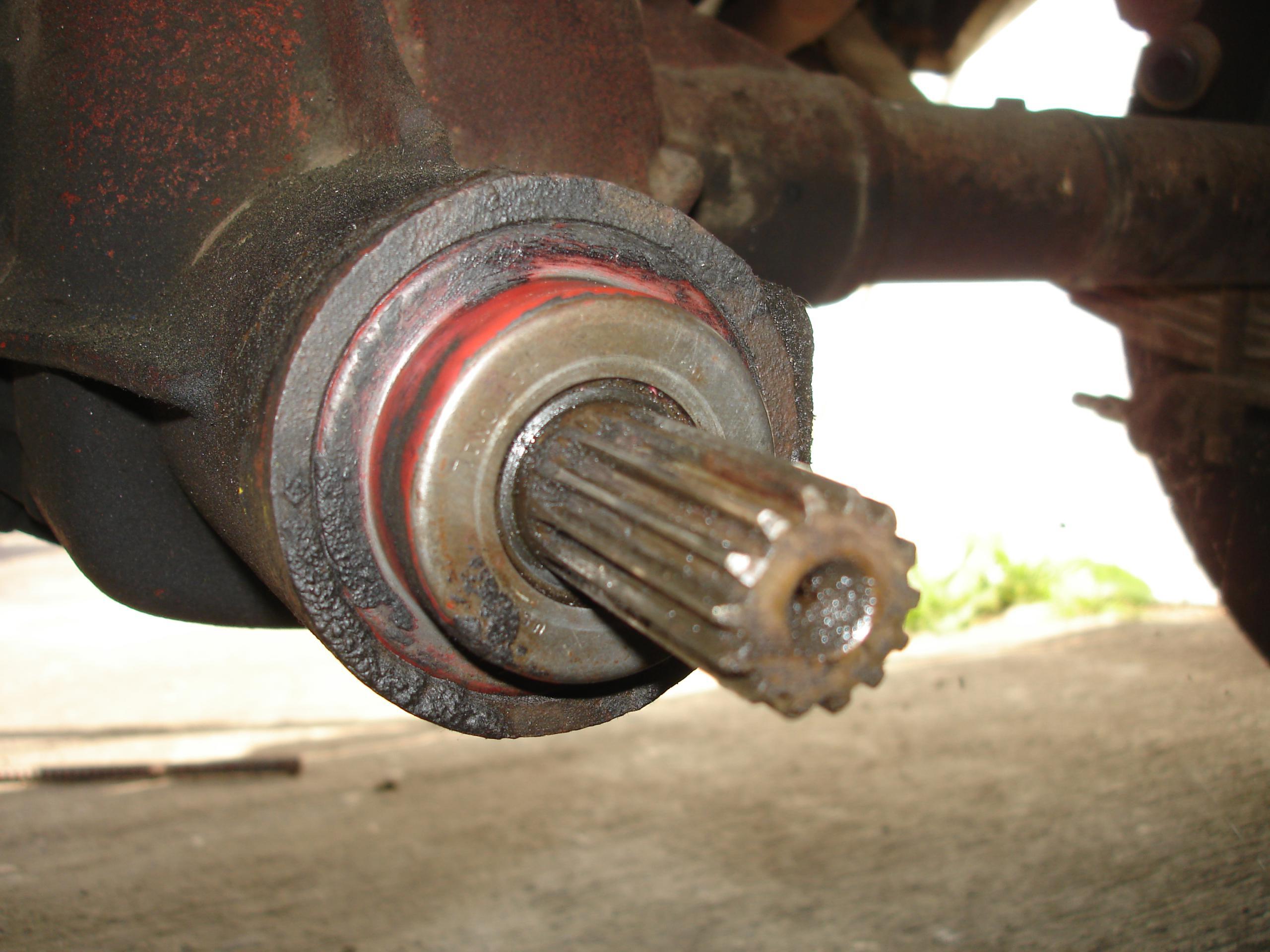
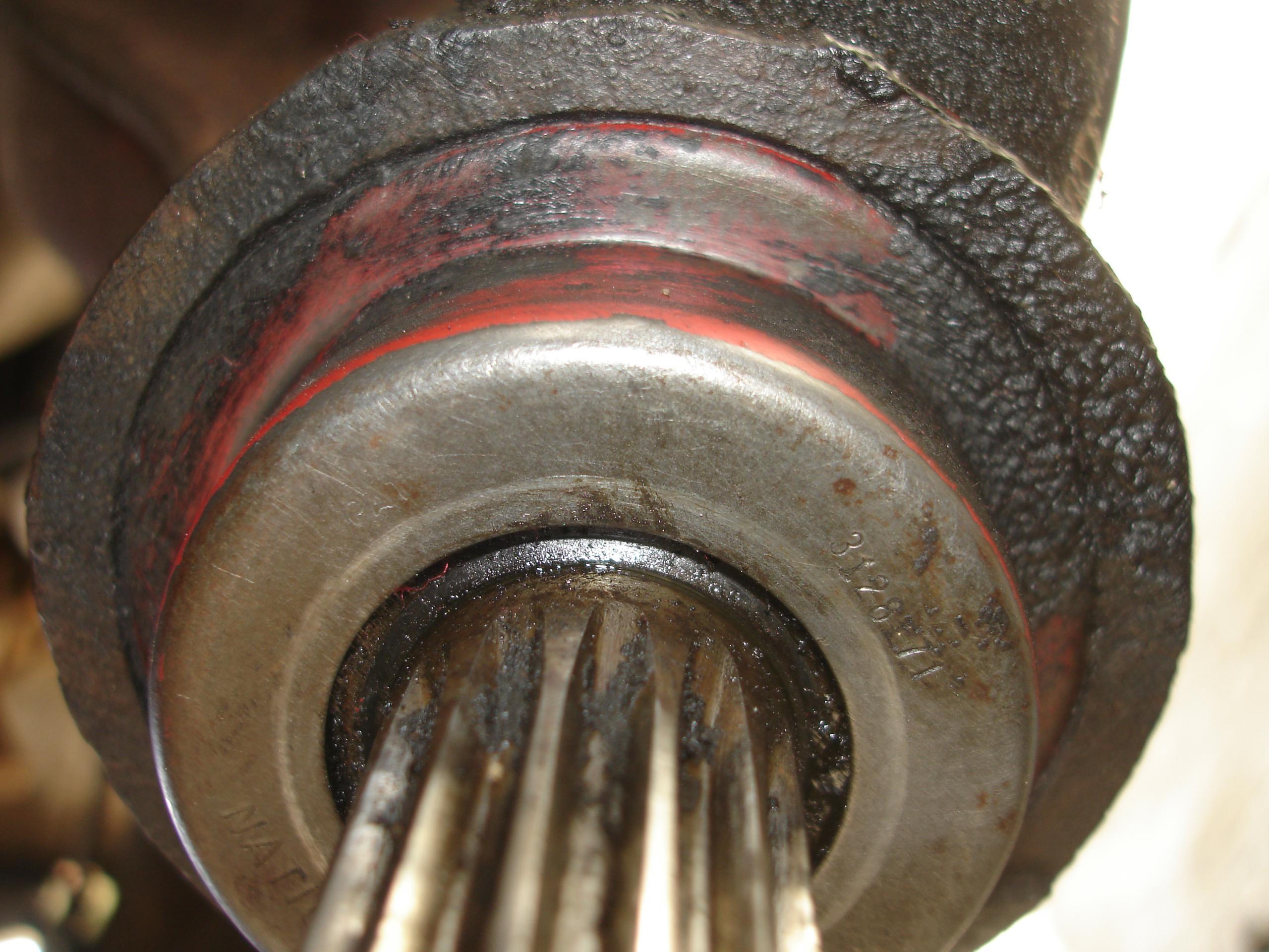
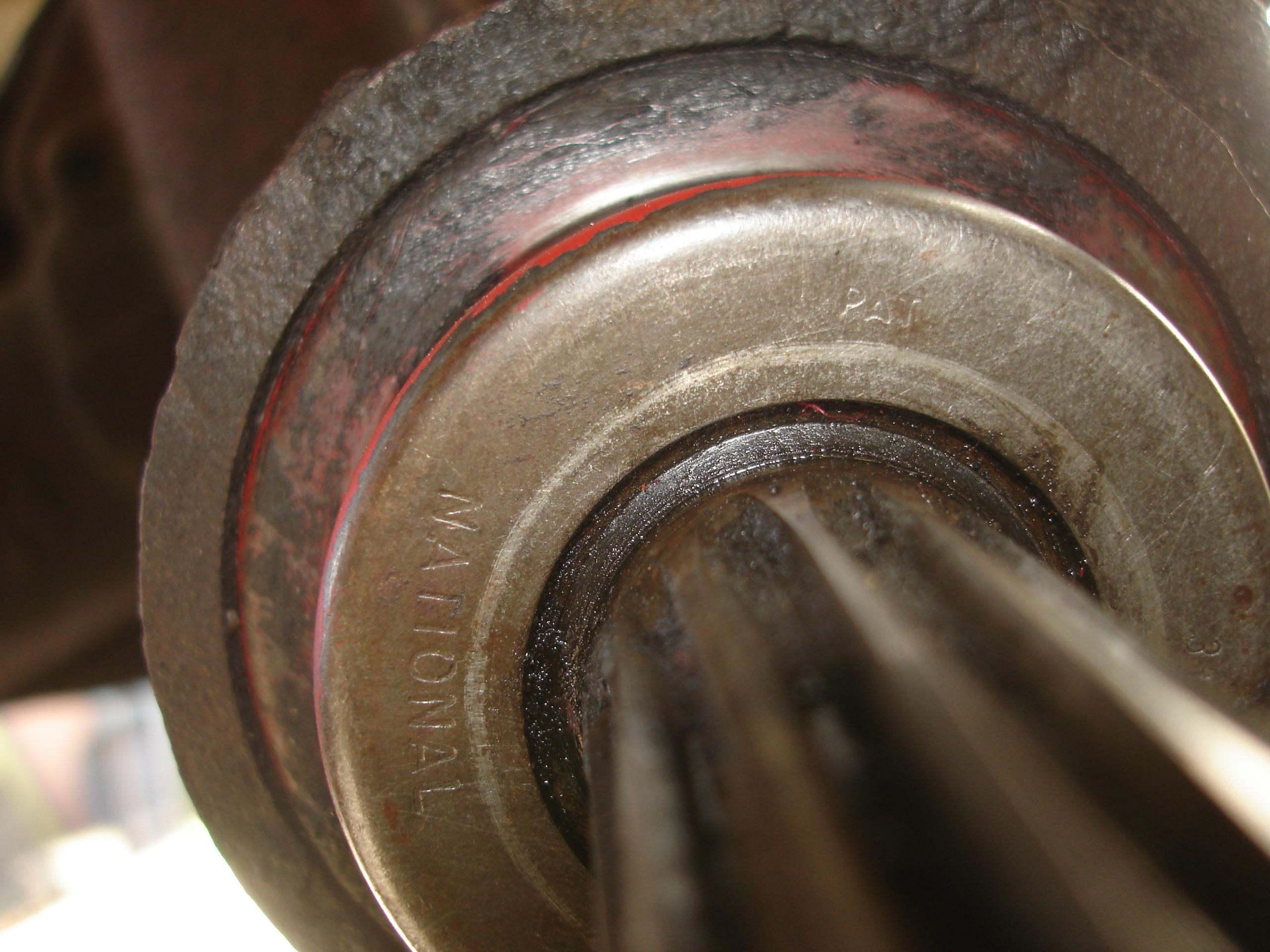
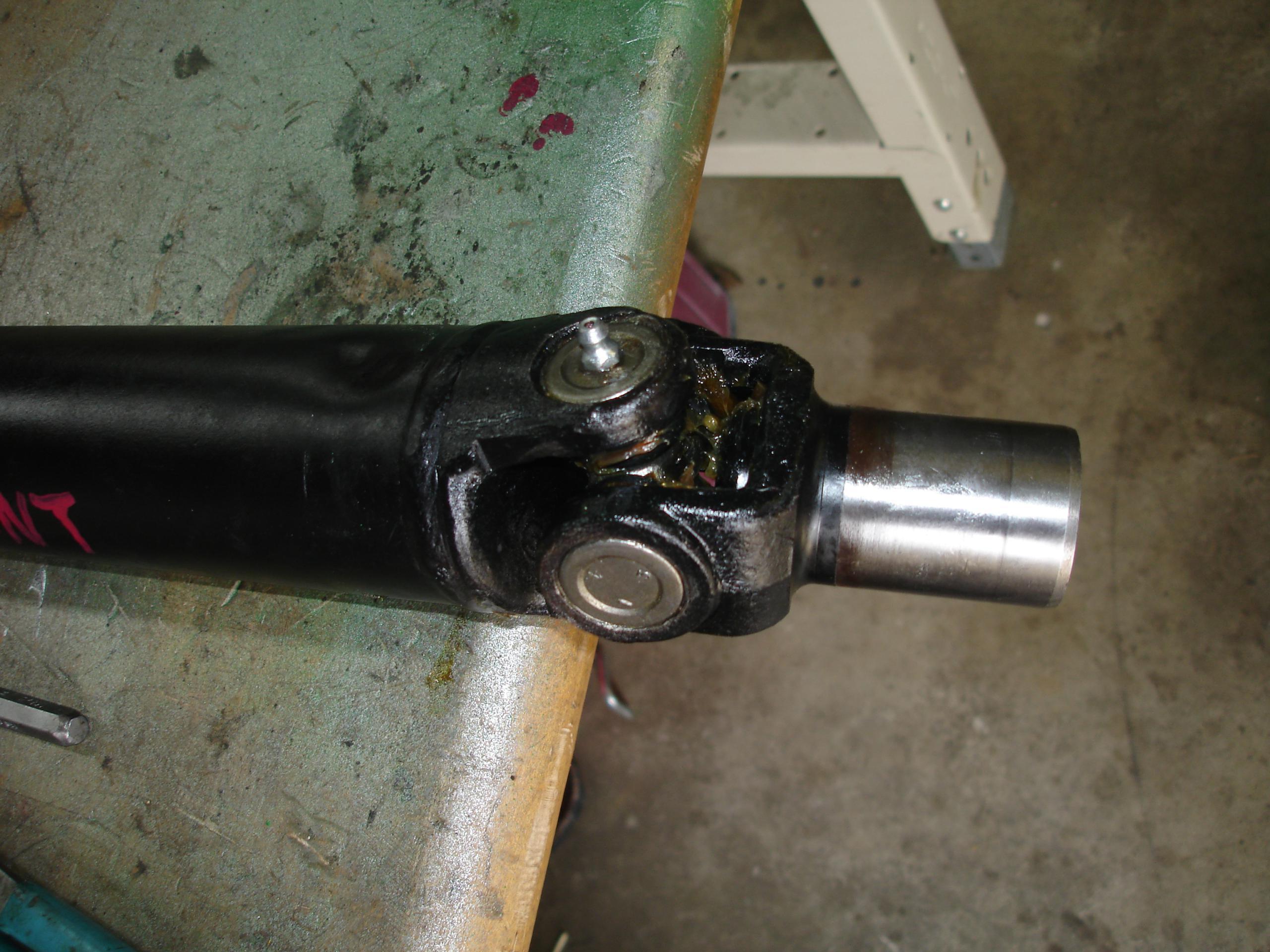
Above you can see the seal dust cover crimped to the big nut. Sometimes these will be missing or loose. If loose the crimps can usually be tightened with a punch and hammer. In some cases you may need to epoxy or solder the cover to the nut. The seals are now hard to find — I’d not want to remove the protective shield.
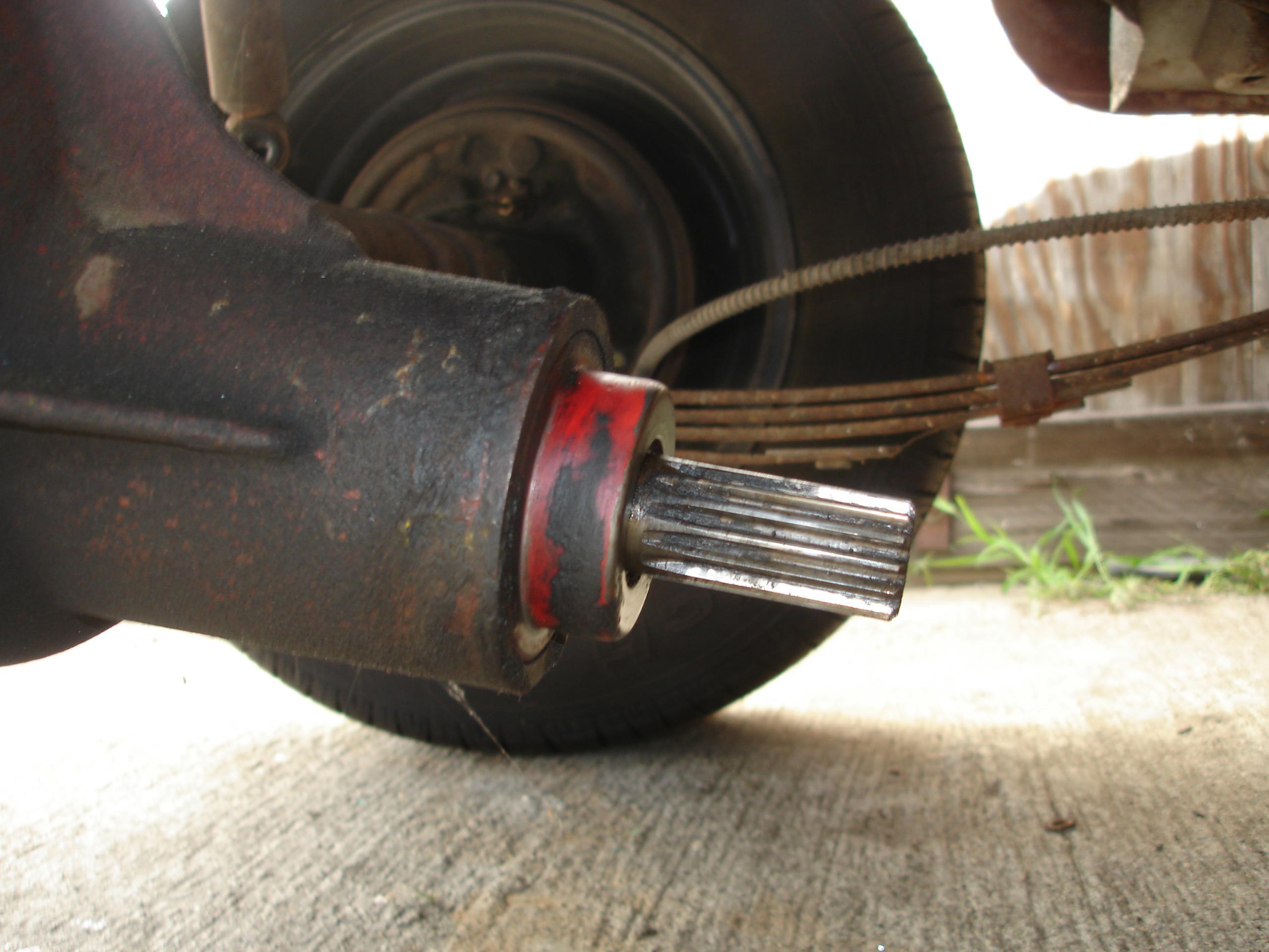
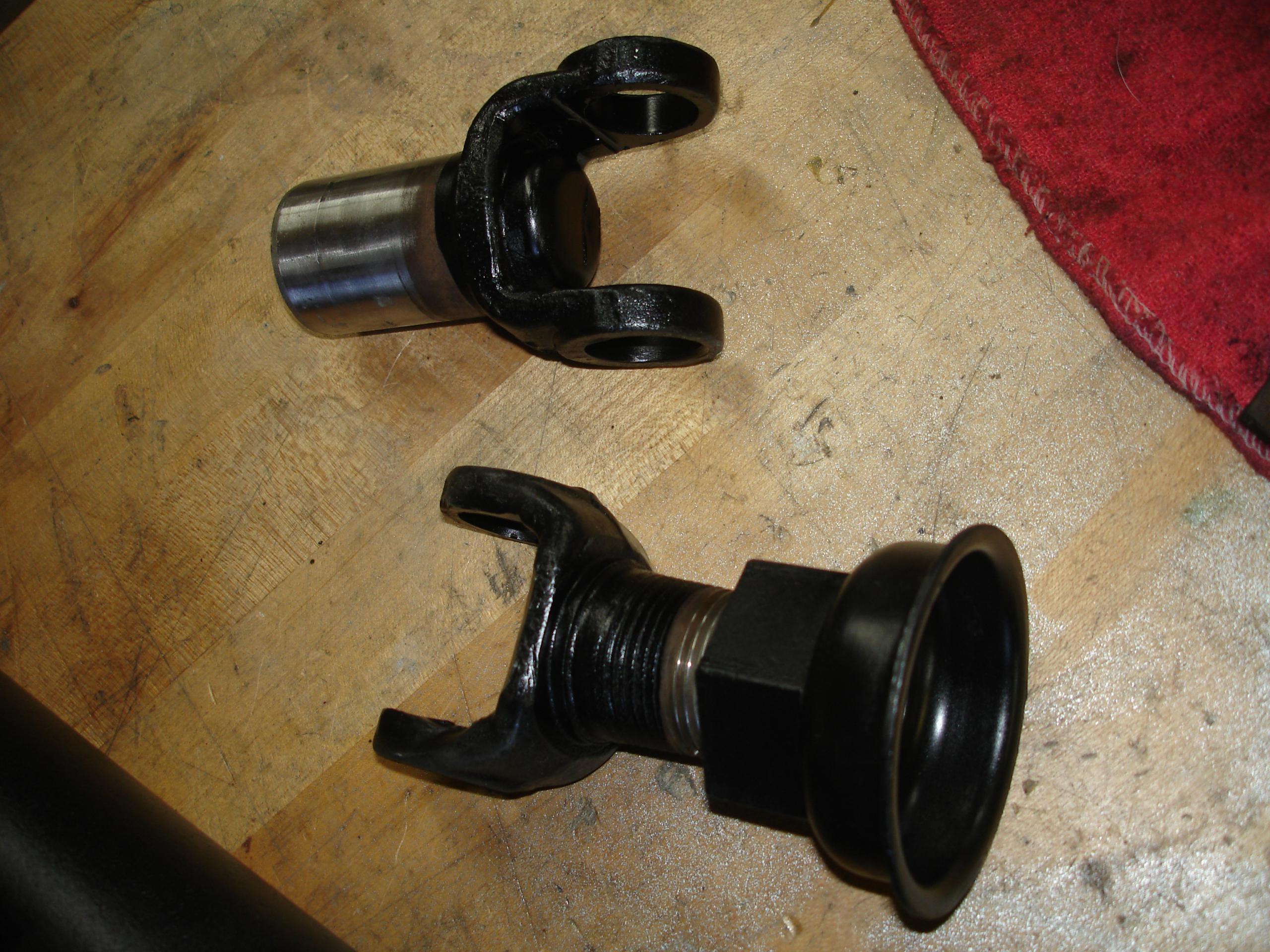
Below you can clearly see the rather severe taper on the collar. That’s two six-inch rulers parallel to the threads.
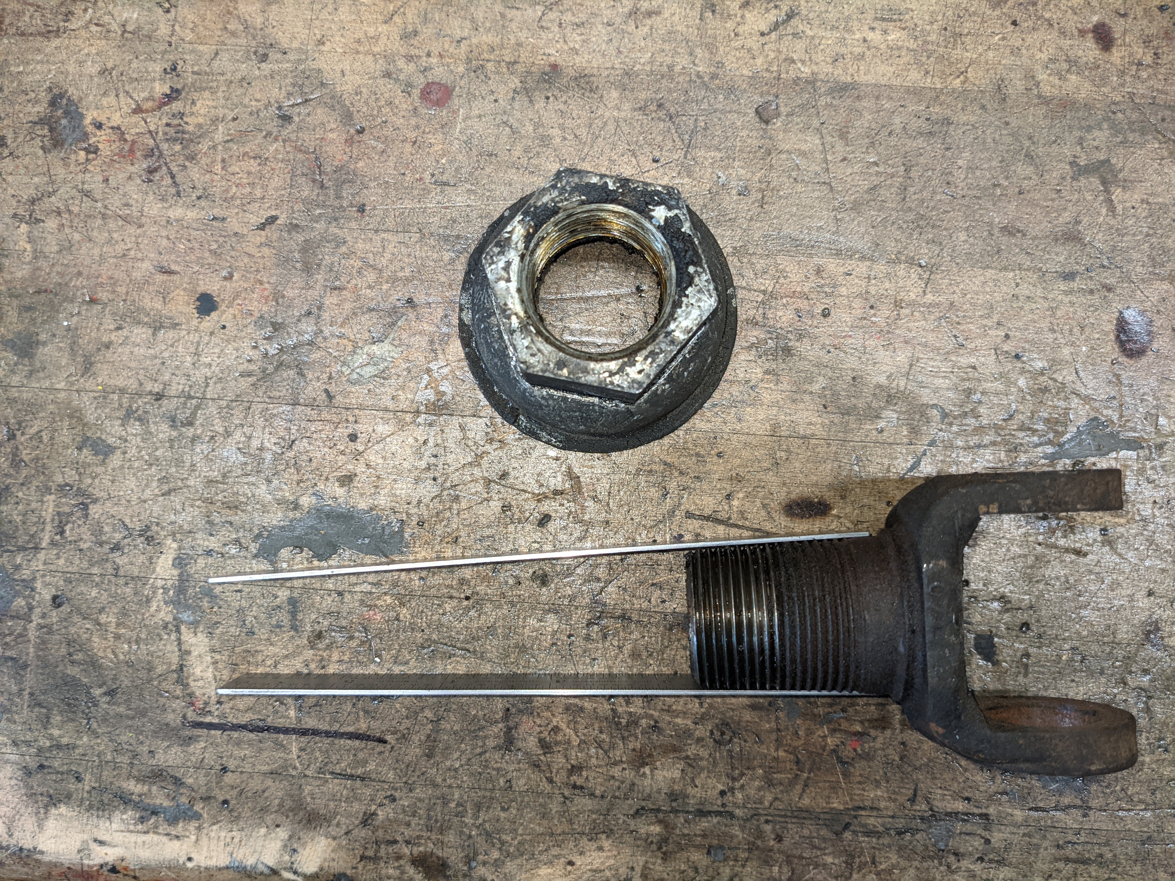
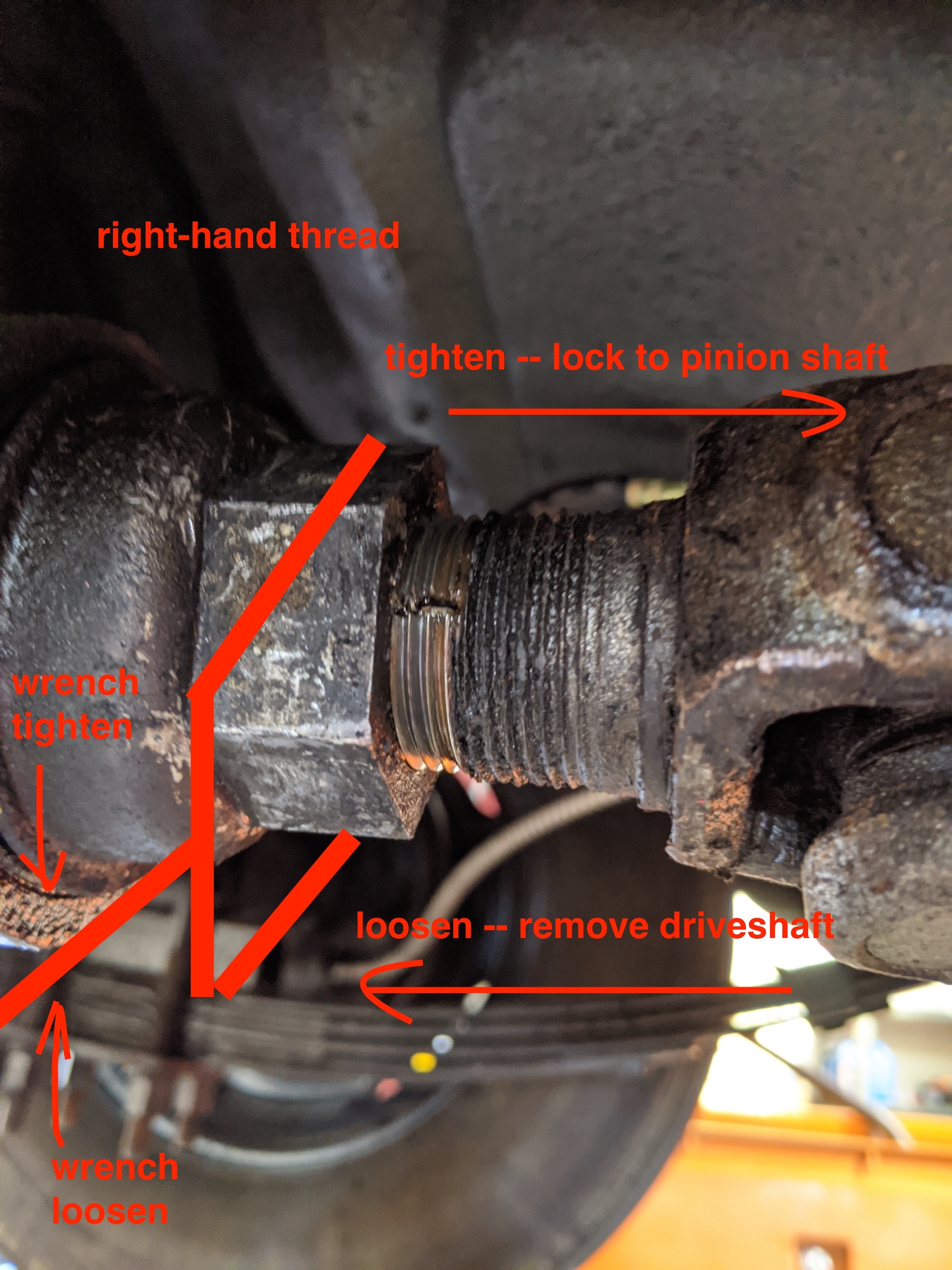
It’s not quite obvious how this assembles. Here’s a key:
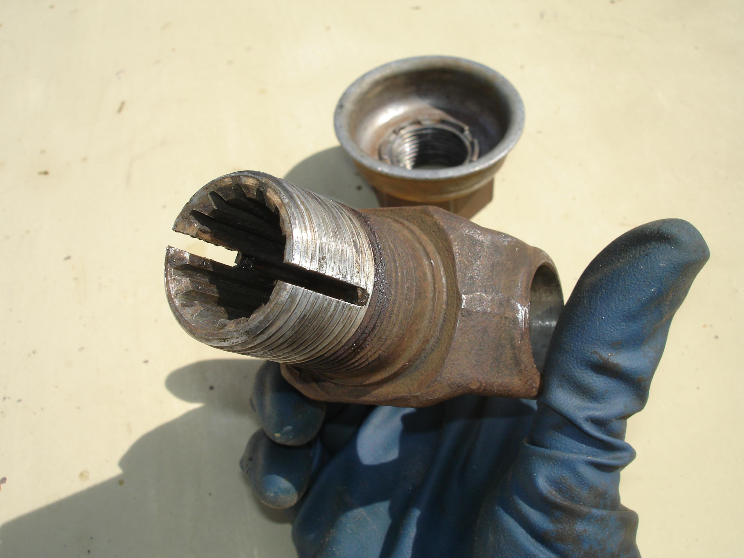
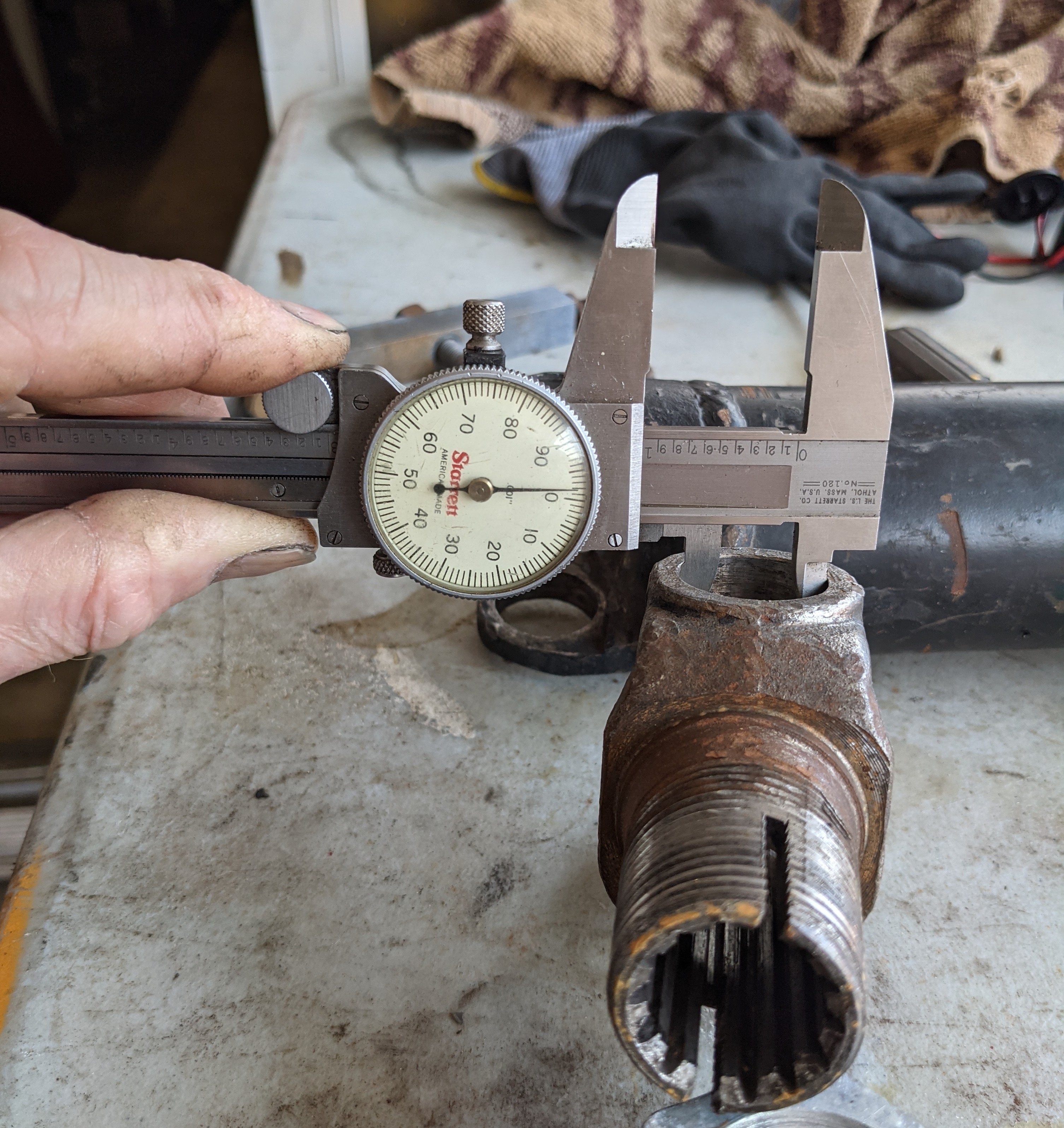
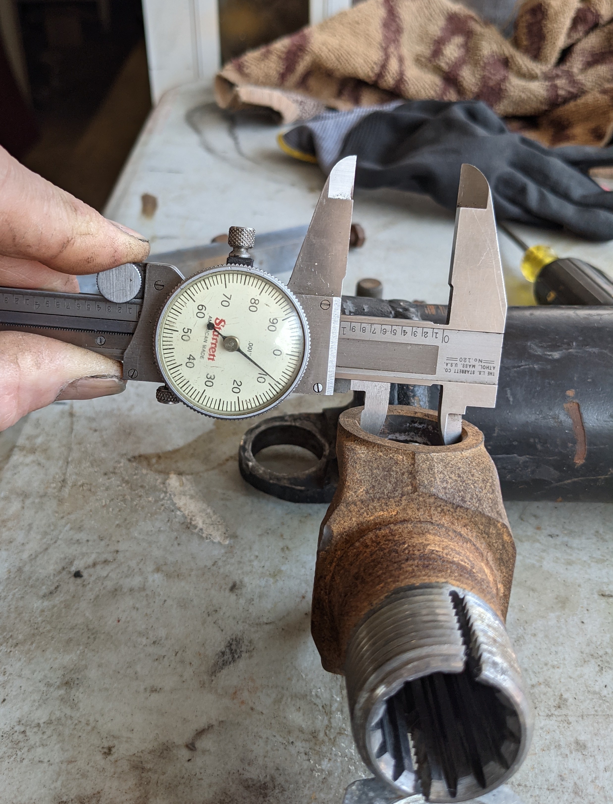
Check for wear/U-joint size
I do not know what is going on here. The Spicer 514G U-joint has cups 1.00″ diameter, and the yoke has a 1.00″ diameter hole. Cups are a press-fit into the yoke, and retained by inner C-clips. I have a yoke here however with 1.009″ bores. It isn’t simply stretched or damaged, the holes are round, no deformation or damage. It’s a puzzle. The cups are loose in the yoke, and rattle. This combination would certainly cause noise and vibration issues, and probably worse problems. The cups should be a snug fit. The bores in the driveshaft ends are likewise 1.00″.
Driveshaft removal
To get the driveshaft out of an assembled car requires a bit of fiddling.
STEP ONE is to loosen the big nut’s grip on the yoke. Refer to the photos below; the tapered splined sleeve portion is severely tapered. Driving the nut towards the front of the car (right hand threads) tightens the yoke’s grip on the pinion shaft. This must be loosened. It is tightened to 300 foot/pounds of torque. This is five-times the recommended torque on a wheel lug nut, and requires big wrenches. Please do not use pipe wrenches, they ruin the metal, but it’s your car.
Even with a professional shop’s floor lift this is not easy. The nut is also frozen on with rust and congealed grease. I think this method below is easier than the car on the lift. It is tedious, but easy, and safe. It requires the big wrenches.
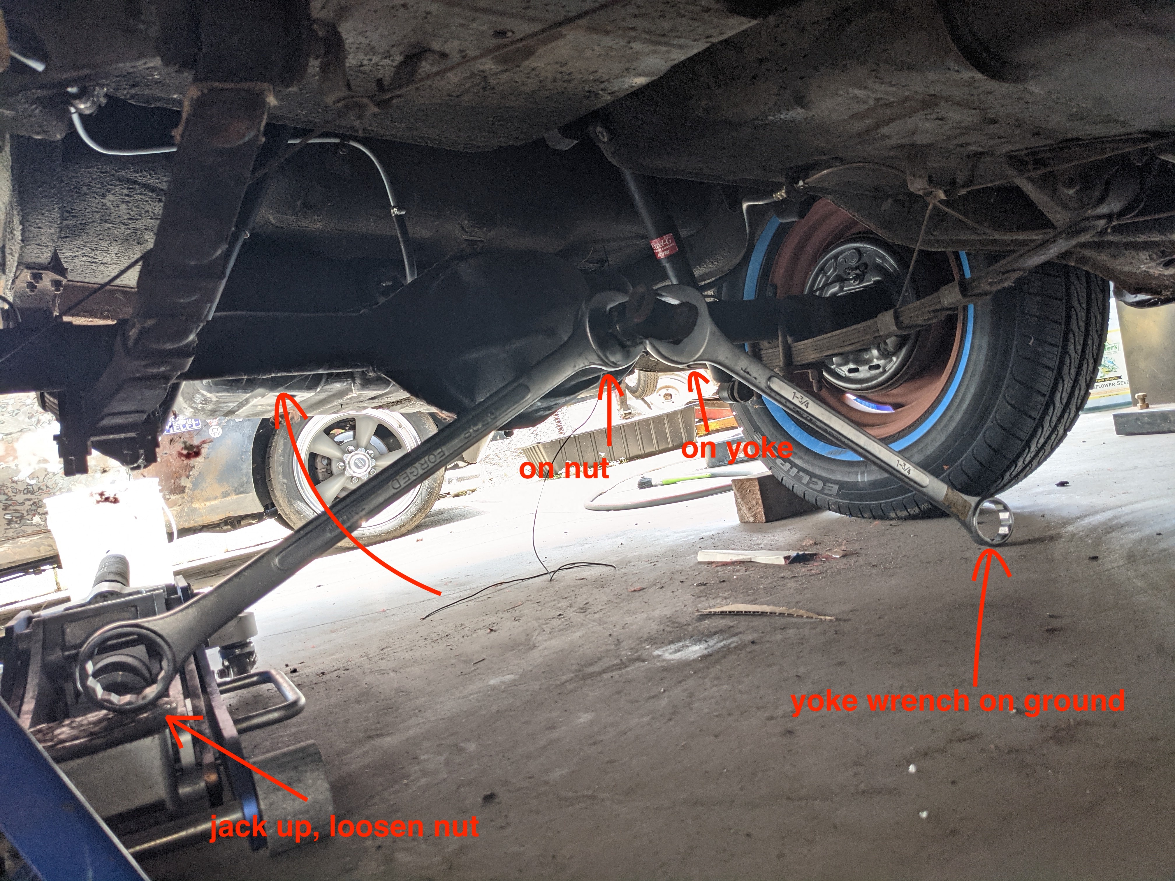
Jack the car up on one side, on jack stands. Good ones, you will be applying lots of torque directly to the entire car. One wheel needs to be able to turn so that you can rotate and position the yoke.
TO LOOSEN: Put one wrench on the yoke, brace it on the ground solidly. Put the other wrench onto the nut and the far end onto the pad of a floor jack. This takes a bit of finesse, to take up all the slack, have the yoke wrench not fall off, etc. (use clamps, elastic, tape, whatever). Then simply jack the end of the wrench. With the car’s sills 16″ off the ground, this ought to get you about 15 degrees of rotation, enough to flop the wrench over (now you know why they are angled like that, if you did not know before). Repeat.
STEP TWO is to get the drive shaft out. Even with the yoke’s death-grip on the pinion loosened, the drive shaft generally does not have quite enough fore/aft slack to come out. The following will provide that additional space:
With the car sitting on its tires, un-bolt the front spring eye perches, both sides, four nuts on studs, and remove the screw holding the brake line support, where the steel line meets the rubber hose. Disconnect the parking brake, at the adjusting rod. I forget if you need to remove or loosen the shocks. Now jack the car up just high enough for the front spring perches to exit their studs. The axle assembly sits on the tires. Now roll the axle assembly back, carefully, the two or three inches necessary for the driveshaft to be removed.
Assembly
If you took it apart, assembly is fairly obvious; insert driveshaft, push axle forward, wrestle the spring perches back onto their studs. It can be difficult to push the axle forward from under the car; I use a ratchet cargo strap as a low-grade come=along. Works great.
If you didn’t take it apart, as is common these days buying old disassembled abandoned project cars, or finding someone disassembled the rear U-joint to get the shaft out (my most recent case), or other crazy solutions applied, improvise. In my case, the axle is in place, I will install the driveshaft as a complication of transmission installation.
TO TIGHTEN: The same two-wrench/floor jack trick works, from the other side of the car. Before tightening the big nut, set the distance from the centerline of the U-joint’s cups, to the face of the axle housing casting, to 4-3/16″ (1958-63 TSMs).
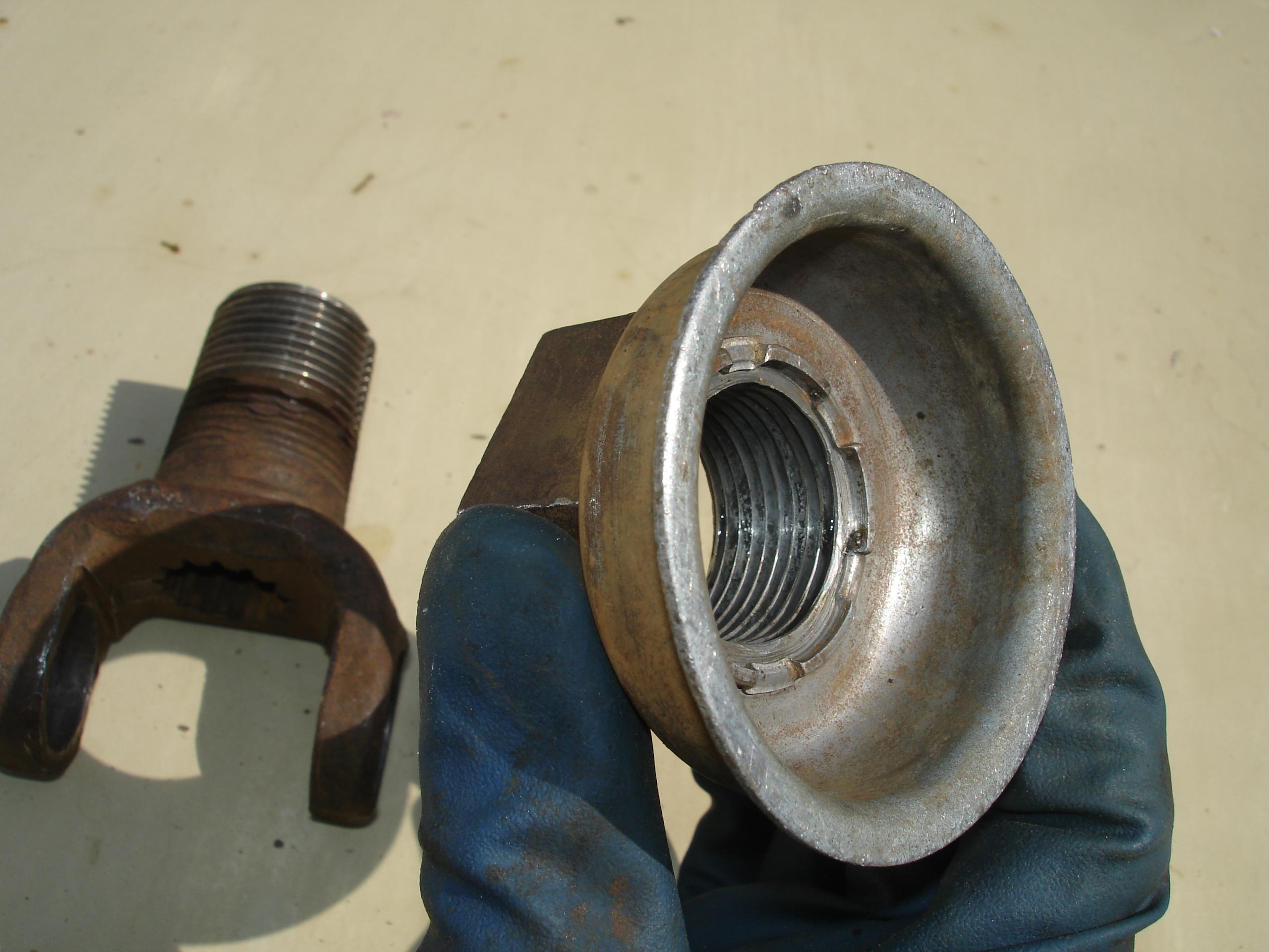
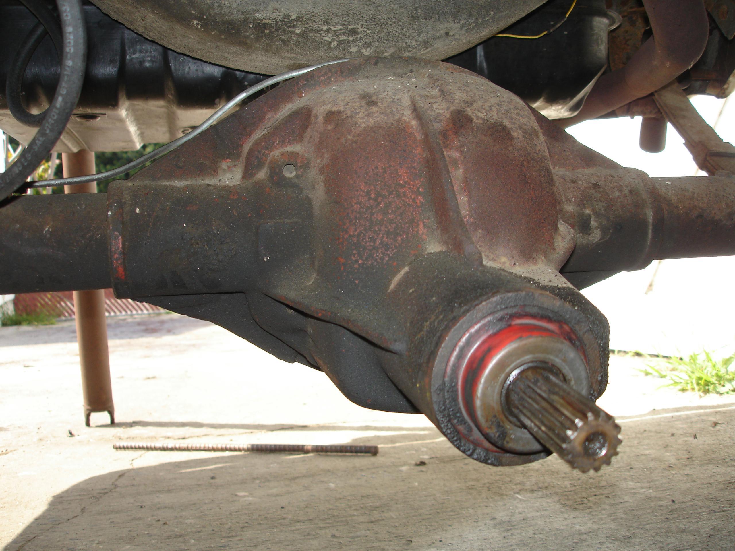
Pinion seal
Replacement seals may be available from AMC parts sources, such as AMC Acres. It is made by National and has an AMC part number of 3128171. It is Group number 9.064. The factory parts catalog shows that number superseded by 320 3580. Even if you find an NOS seal you probably don’t want to use it — old rubber doesn’t usually last long.
25 March 2021 update:
… the pinion seal used on this rear was mysteriously used on 68-69 Javelin Sixes and is presently being reproduced by the vendors. It is available at American Parts Depot for $39 and bears the part number 990 6402B. AMC Acres has is under part number 09-3580. I believe the other vendors have it as well.
This is the pinion end of the rear axle. I took these photos to later identify the seal, which are apparently no longer available. It doesn’t look like rocket science to adapt something to though.
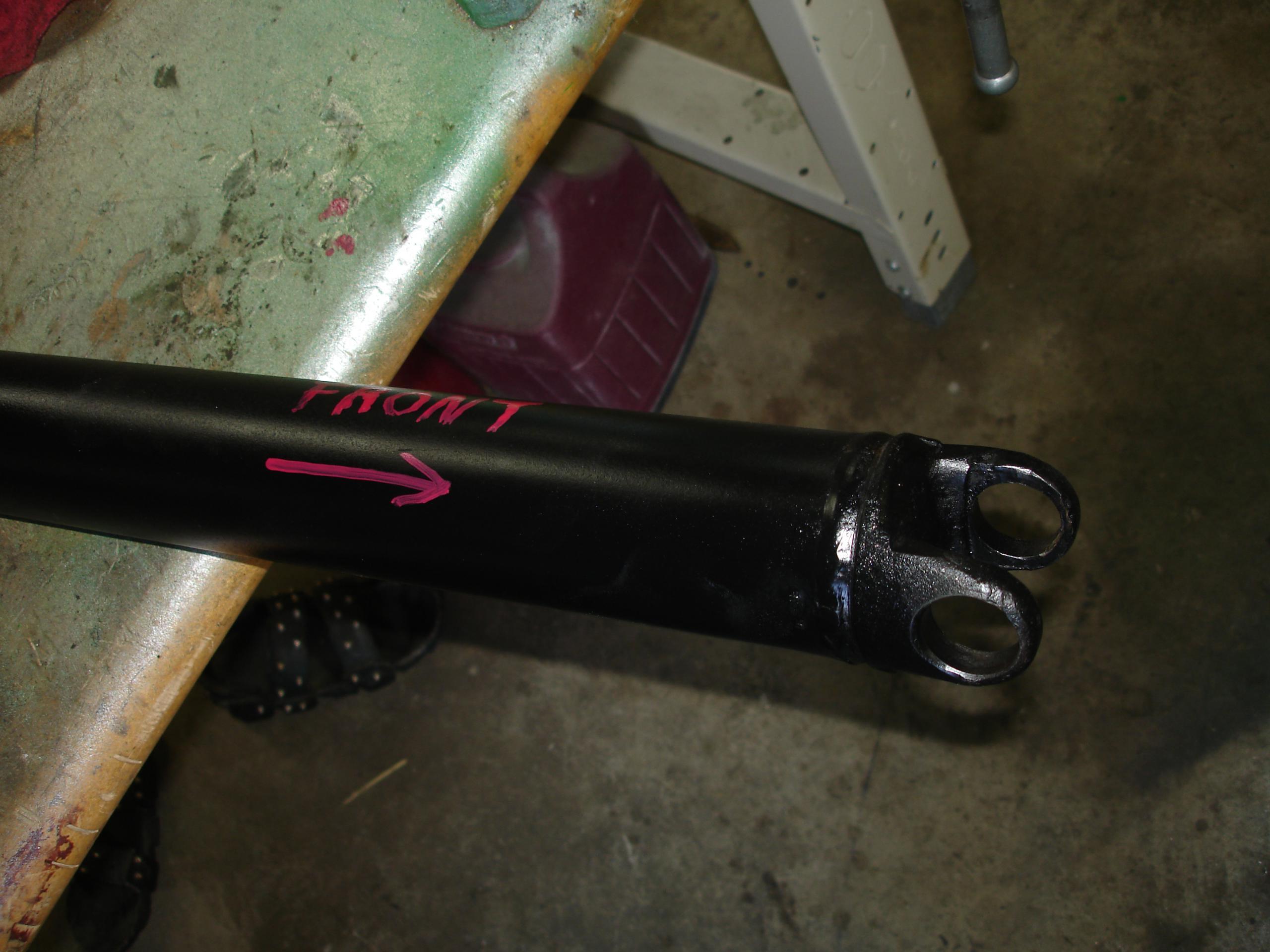
Ready to install.
The Easy Way
(by Frank Swygert)
If all you need to do is remove the driveshaft you DO NOT have to remove the “big nut” yoke. It only has to be removed if the pinion seal needs to be replaced, the pinion shaft needs to come out when rebuilding the axle assembly/replacing the pinion gear, or the yoke is damaged or worn out.
It’s not exactly easy to remove the driveshaft under the car, but it can be done with a little patience. A former Rambler dealer tech told me how to do this when I had my first Rambler back in 1979.
This procedure requires weight on the rear axle. A drive-on lift would be ideal. With a two post lift you will have to support the rear axle as if the wheels were on the ground. You can, however, remove the inner C-clips up on the lift (and reinstall them). I usually put the rear axle up on jack stands so I have just enough room to slide under the car on a creeper and the wheels will still turn. It’s tight under there, but I recently did one (October 2025) at 63 years old with no problems.
The reason the wheels need to be on the ground is that when they hang freely from the rear leaf springs the rear axle moves forward, binding the driveshaft between the rear axle and transmission.
With the rear axle supported, first remove the inner C-clips from the u-joint caps that are in the yoke, NOT the caps in the driveshaft. This is important! You can’t remove the shaft if you remove the wrong caps.
Once the C-lips are out remove the caps. With the caps out you can rotate the cross as far as possible and lower the shaft out of the rear yoke. I do this by using a hard rubber or wood mallet (or a regular hammer with a block of wood between the shaft and hammer) and knocking the driveshaft to one side, removing the cap, then knocking the shaft to the other side to remove the other cap. Sounds like a bad idea, and it will be if you’re not careful. Make sure you hit the shaft near the yoke end where it’s solid, right over the weld that holds the end on. DO NOT strike it back on the shaft side of the weld. You could dent it back there and cause an imbalance in the shaft. Make sure to keep the cross inside the caps as you work or you could dislodge the needle bearings. If you’re replacing the U-joint that’s not so important when removing the caps, just when installing the new ones.
Reinstalling is the reverse of the above. You can tap one cap in with a small hammer, then put the cross partially in the cap and tap the other one in. Once the C-clips are in I always take a flat screwdriver or small punch and make sure the clips are seated in the grooves of the caps. I neglected to do this once years ago and the C-clip came out… then the cap came out… then the driveshaft slung out from under the car before I knew what was happening — five seconds or less. So I make sure the clips are seated since then!
Website contents, unless otherwise specified, © 2025 by Tom Jennings and Frank Swygert. Permission is granted for personal use with no remuneration. Corporations or any legal organization or their agents (employees or consultants or other relationships) expressly prohibited without written permission.
Deprecated: File Theme without comments.php is deprecated since version 3.0.0 with no alternative available. Please include a comments.php template in your theme. in /home3/amcmagc1/public_html/wp-includes/functions.php on line 6170
Leave a Reply