

written by Tom Jennings 09-15-2022, edited by Frank Swygert 06-14-2026
Crankcase ventilation is absolutely necessary. Even the best rings in the best engines don’t seal perfectly. Water vapor is a major combustion byproduct and it definitely ends up below the rings and needs to be removed before it condenses and ends up in the oil.
AMC tried out various crankcase-ventilating schemes between 1956 when this engine was new through it’s final year in 1965. This was originally a road draft system; a 1″ or so tube angled down toward the ground with the lower end near the bottom of the oil pan from the center of the front side cover where a mild vacuum would be generated by the car moving along the road and fumes would be drawn out. Mainly it served to spray dirty oil and mist over the chassis and of course the roadways and the air, especially as the engines got some miles on them. Older drivers well recall the black stripe down the middle of every roadway — almost every car manufacturer used road draft systems before the mid 60s. Adding to this mess was that in some years the valve cover has vents at both ends that both let air in and oil mist out, at random as the engines aged. Road draft tube shown below.
The goal of crankcase ventilation
Piston rings do not seal perfectly when new, and leak more with wear. The major chemical components of ring blow-by are air, exhaust, water vapor and fuel (reference: Blowby Gas Composition in SI Engines.pdf by Karel Pav of Skoda Auto). Added to this is a large volume of lubricating oil mist generated by the whirlwind of crankshaft and connecting rod motion. If there were no oil mist, crankcase ventilation would be a lot easier.
Water vapor is about 4% of ring blow-by (see referenced paper) and ends up in the crankcase. It’s not a liquid until it condenses, which requires removing heat. In an active ventilation situation (PCV) the water remains a vapor and is sucked into the intake (which already has ordinary atmospheric water vapor anyway).
Positive Crankcase Ventilation, aka PCV
The first PCV systems weren’t for pollution control like today. It was first used in military vehicles in the late 30s and the 40s (WW II) so that engines could operate under water without getting water in the crankcase.
The PCV system was designed to re-circulate the gases into the air intake so that they could be combined with the fresh air/fuel and get more completely combusted. In 1961, California regulations required that all new cars be sold with a PCV system, specifically as an emissions control device, the first emissions device required on a road vehicle.
Starting with the 1963 model year, most new cars sold in the U.S. were so equipped by voluntary industry action so as to avoid having to make multiple state-specific versions of vehicles. PCV quickly became standard equipment on all vehicles worldwide because of its benefits not only in emissions reduction but also in engine internal cleanliness and oil lifespan.
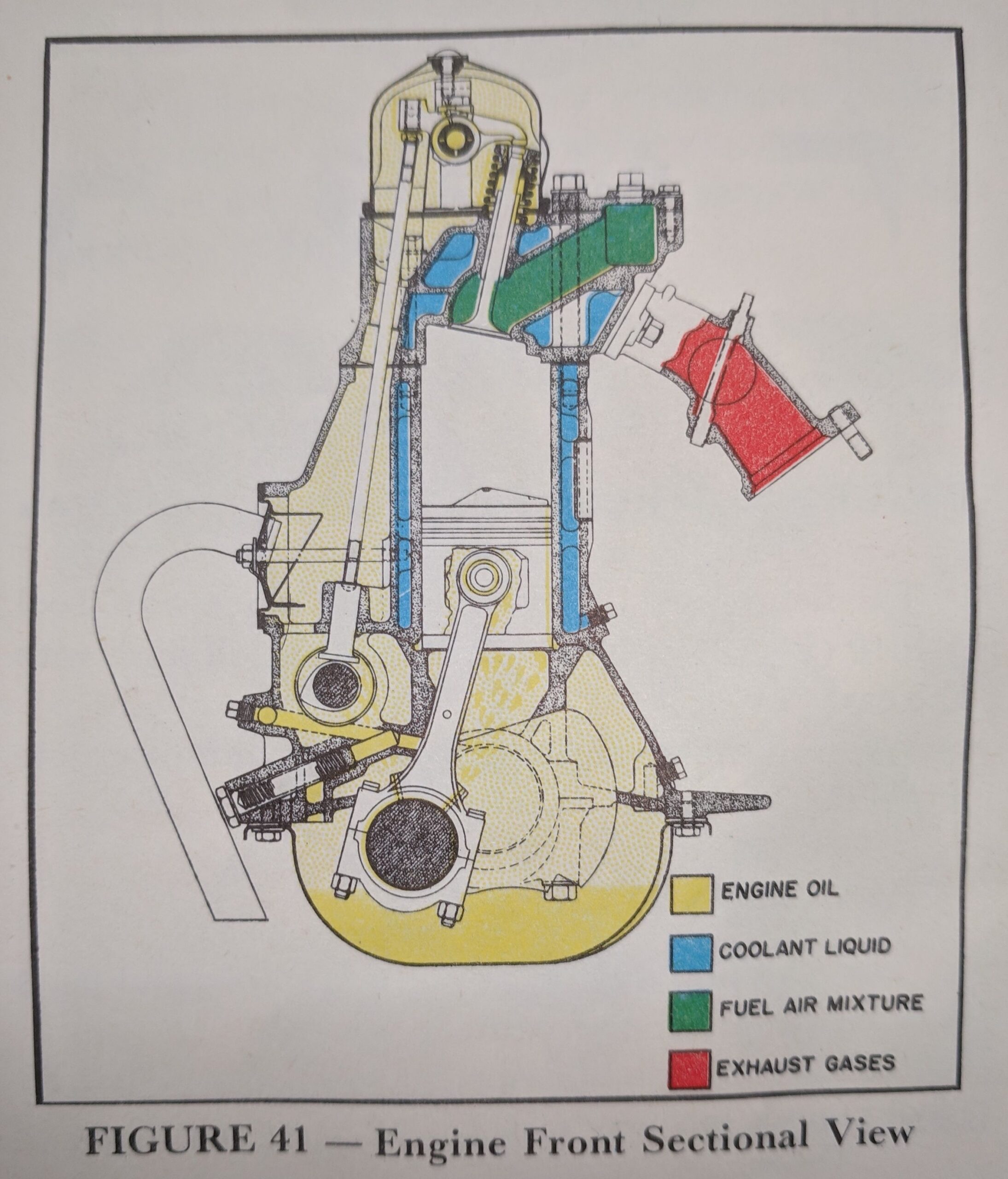
This illustration (below) from the 1962 TSM shows the side cover with 1/2″ hose nipple, the most commonly seen system on most 195.6’s. The PCV screwed into the edge of the L-head (at least in 61 and 62) but on the OHV it’s on a brass street elbow with the valve horizontal in the line which runs to the front of the engine and under the thermostat pod.
Looking at an actual engine you might assume that the baffled side-cover location would be fairly free of mist and flying oil, but you would be wrong. Every system I used had much oil mist out that cover. In addition the covers leak very nicely. This system works poorly; I doubt it can clear the crankcase, there are too many openings to the outside (oil filler, two locations in the valve cover).
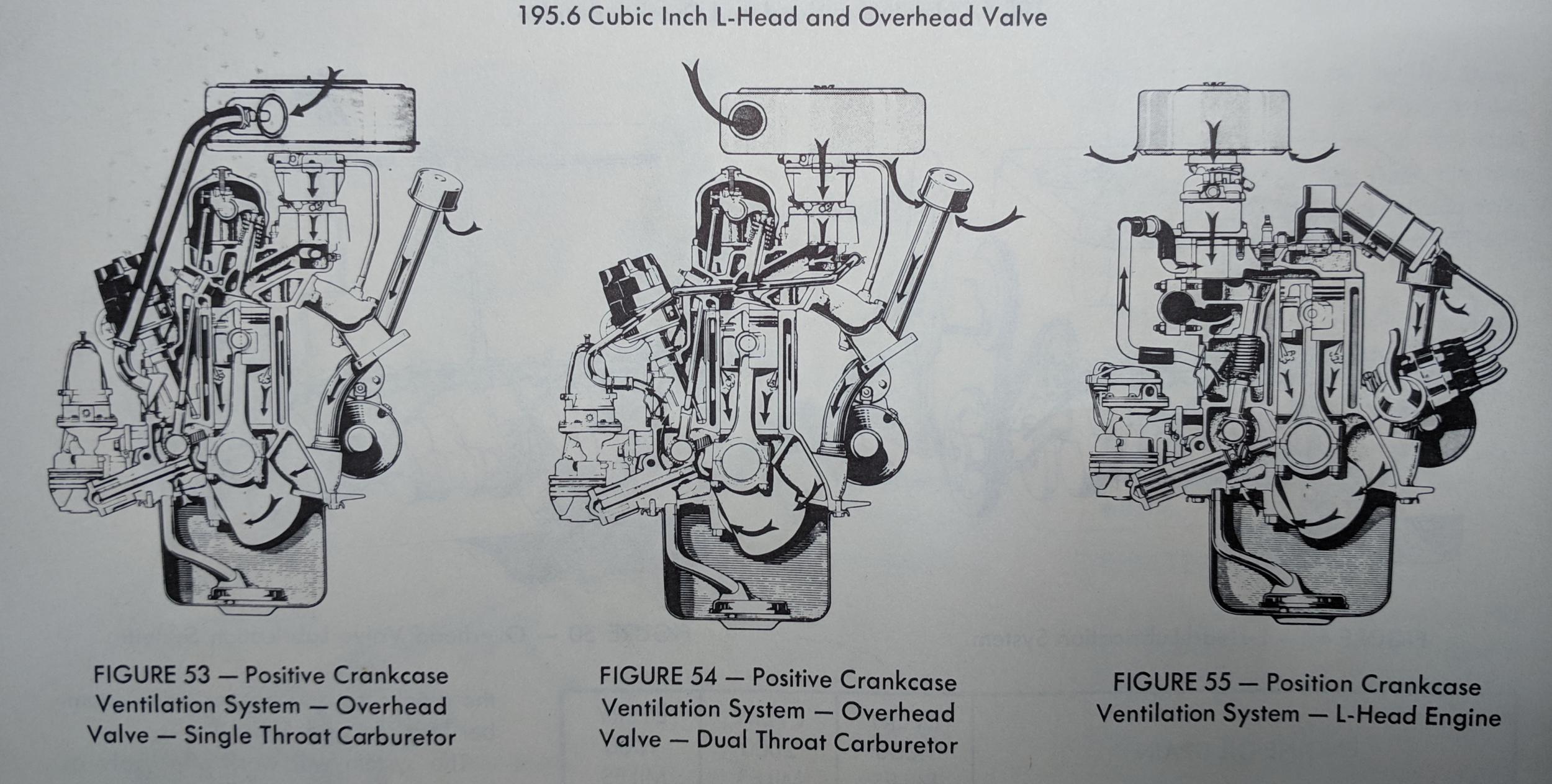
Final model year 1965 had more or less all of the PCV variants available at once. 1V carb OHV, 2V OHV, and L-head each had their own arrangements. The drawing below is detailed and acccurate, but very hard to read even in print; suffice to say in real life it looks like most 1960’s..1970’s PCV system. No big deal here. However:
- 1965 valve covers do not have vents (some are chromed).
- 1965 1V carb engines have “sealed” oil filler caps.
The above two components are desirable for an improved PCV system. Of course everyone knows that the chromed valve cover makes the car much faster.
PCV system experiments
In the last 10 years (~2012-2022) I did a lot of experimenting with PCV in my roadster to clean up the engine compartment and keep oil mist out of the intake. Most of the problems I had I created myself by doing foolish things with the engine, like using it in a sports car environment, sloshing oil in every hard turn causing oil pressure loss (air under the pickup). I ran an extra quart of oil for a while (which made more mist since there was more oil to slosh around) and finally settled on an expensive Accusump system. That solved the problem.
The PCV systems below all worked fine, and the stock one does get some oil mist desposited up into the floor of the intake manifold, but it’s not enough to be worth any effort to solve — unless you like to cause your own problems like I do. But the systems below all worked, and if you really need a catch-can then a carefully chosen spin-on oil filter and adapter and hose will set you back $40 in 2020 money, though it won’t say MISHIMOTO on it (a Sharpie will cost you another buck). It will work better too.
The stock PCV system is perfectly acceptable for a normally driven vehicle. You need to make sure you have a PCV valve that is designed to work horizontally, not vertically, though. If you have a road draft tube it’s easy enough to remove the tube (they are just crimped on the cover and many have been lost anyway) and weld a cover over the hole, then a 1/2″ hose nipple in that. You can get the front side cover from a 61-65 model (61-62 California only) and use that, or get another rear cover and put a nipple on it.
PCV, velocity-chamber cover, external catch can/filter
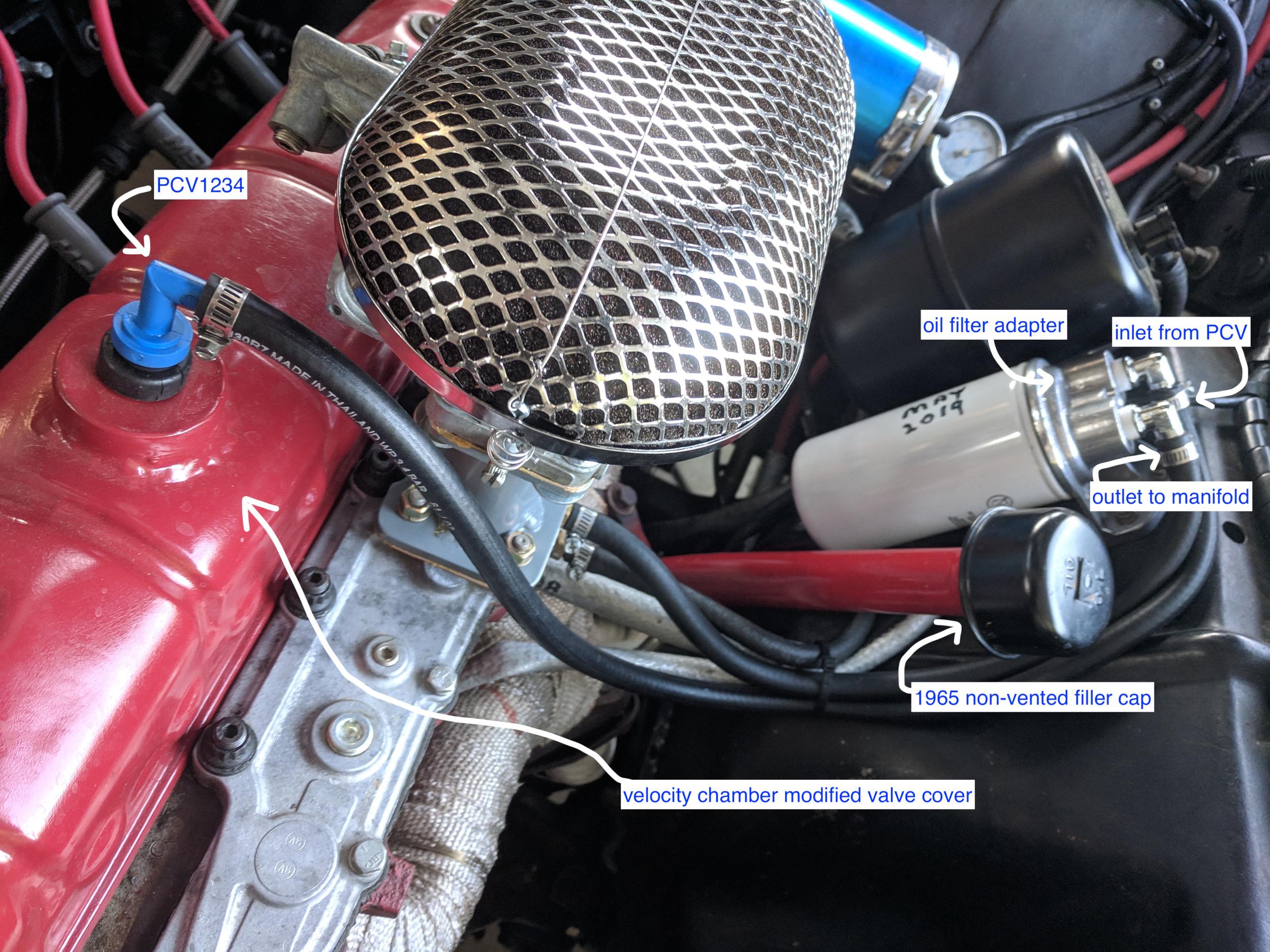
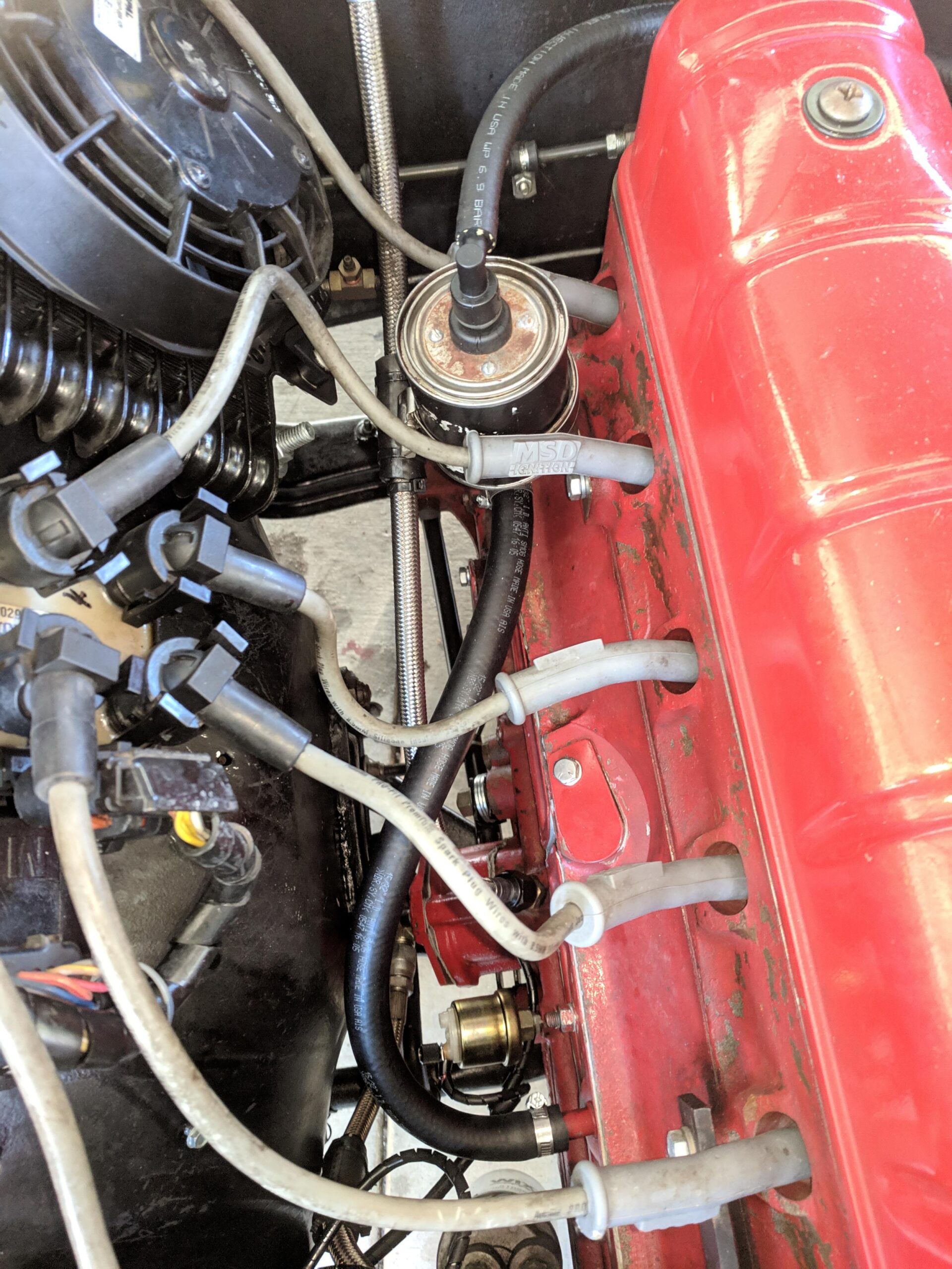
Though the velocity chamber valve cover (details below) by itself was fairly effective, certainly better than stock, it still passed about a teaspoon of oil every 1000 miles or so into the intake (determined by installing a clear fuel filter in the PCV hose). Catch-cans being needlessly expensive, and a life-long adherent to Rambler Mentality, I refused to pay $200 for a pretty Mishimoto “billet” can. Installed below is an inexpensive Derale remote oil filter adapter and a tall filter without an anti-drainback valve (WIX WL10100). The filter is being used mainly as an air filter. Most oil will condense and drain back, and water vapor and other fumes drawn through the filter back into the intake. The filter should be changed periodically, every other or every third oil change. Oil filters are cheap enough.
Catch cans work because they slow the velocity of the gases so that fine droplets coalesce into larger droplets and separate, either via gravity or filter mesh. Depending on where they are mounted they may remove heat too. If cool enough the catch can will also undesirably condense water vapor into liquid. The collected water will trap dissolved gases and particulate matter that would otherwise be better off fed through the intake to the combustion chamber, where it would go out the exhaust. I’m convinced that this is the cause for the alarming catch-can contents in all those YouTube videos — without an aftermarket catch can that junk wouldn’t be produced in the first place. That said, this Engineering Explained YouTube video seems mostly sensible.
Valve cover velocity chamber
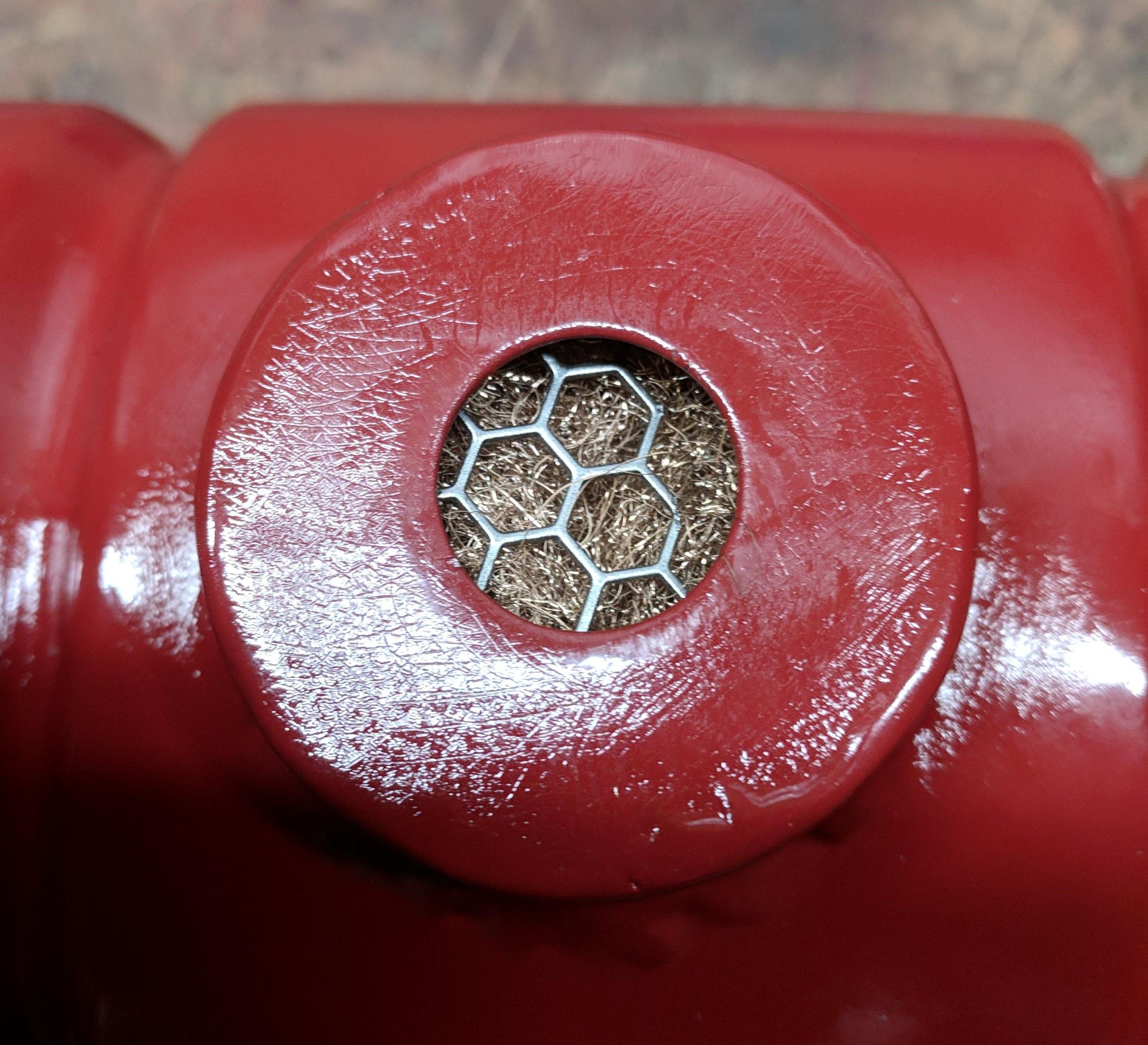
Since the top of the valve cover is the highest point in the engine, and with relatively low oil flow up there, it seems the most sensible place to draw from (the subsequent 40 years of engine design is a big hint too). To that end I built this velocity chamber equipped valve cover. A large internal baffle blocks direct flow to a 3/4″ hole that feeds the “chamber” on top. The chamber is packed with coarse bronze wool. The inner baffle is very wide, the valve cover is relatively cool and provides area for condensing droplets.
The stock cover vents on each end are welded shut and the side cover outlet blocked. With the engine running and my hand sealing the oil filler neck tube this rapidly draws solid vacuum at idle. Construction details below.
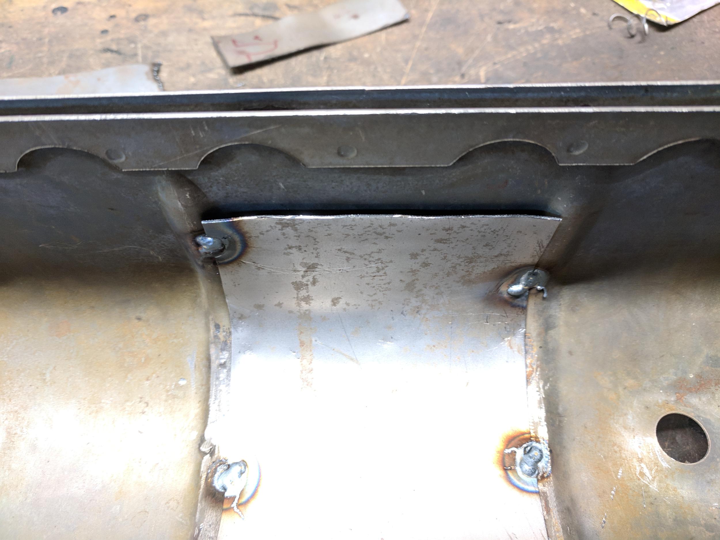
These first two are of the internal baffle. Just a piece of sheet metal tacked in. Make sure there is room to draw vapor on each end. The baffle is welded on top of the ribs so there is just over a 1/8″ gap between the cover and baffle. The sides should just start to curve down the sides of the cover.
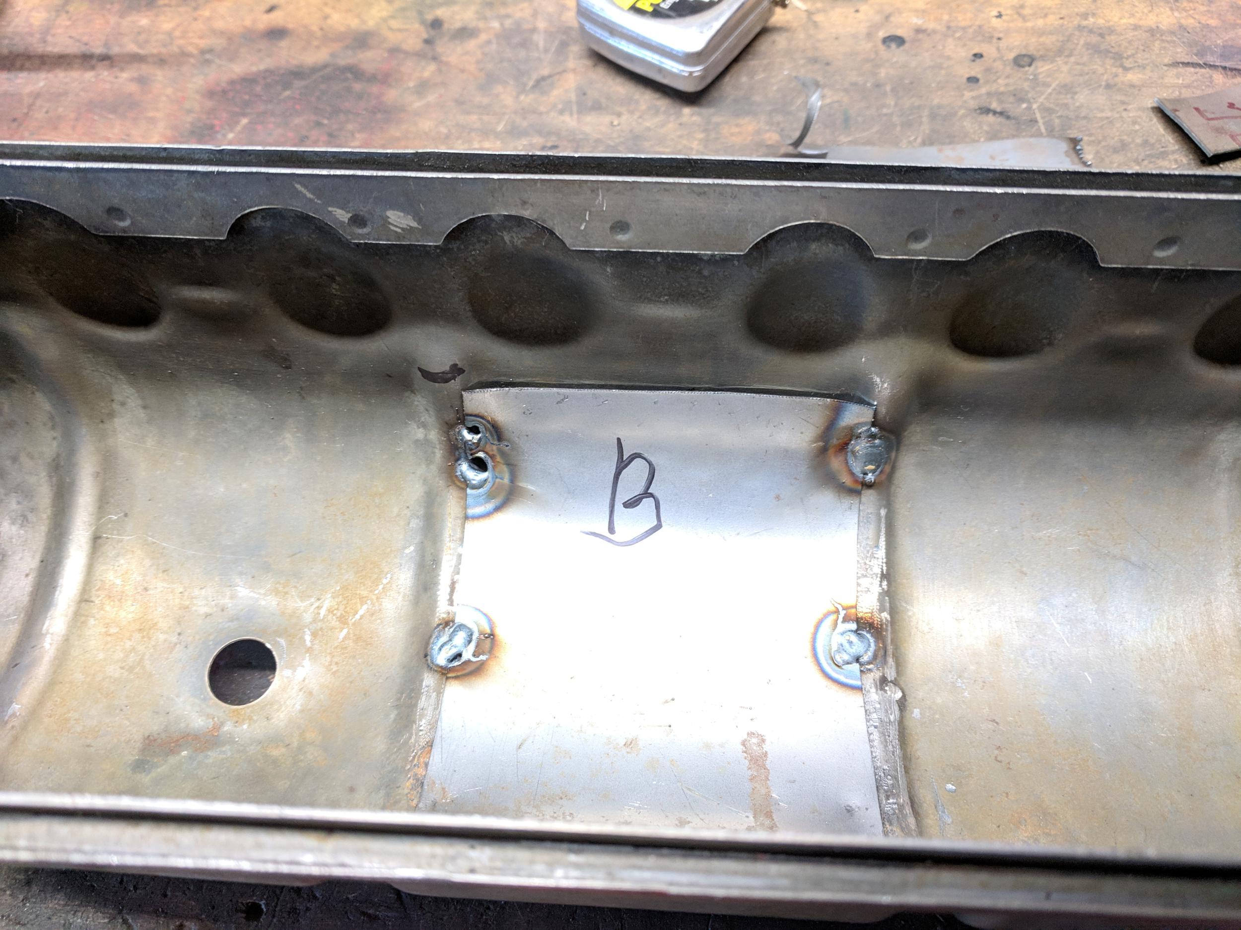
The draw hole was placed in the front most full ribbed section. The draw hole and two drain-back weep holes live under the fitted velocity chamber which was welded onto the cover. The 1/8″ drain back holes need to be to the sides — the lowest part under the chamber, and inside the chamber. Any oil that gets in there can get back out.
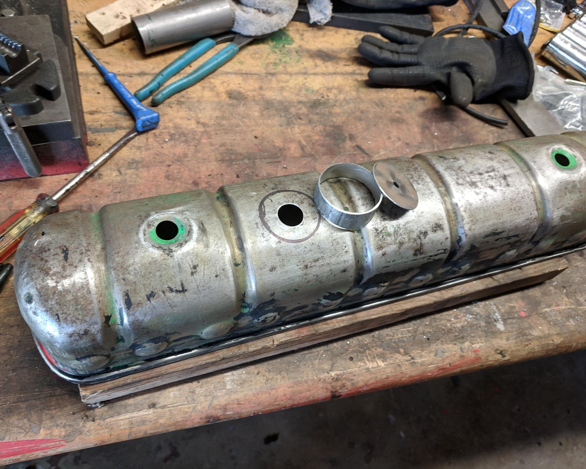
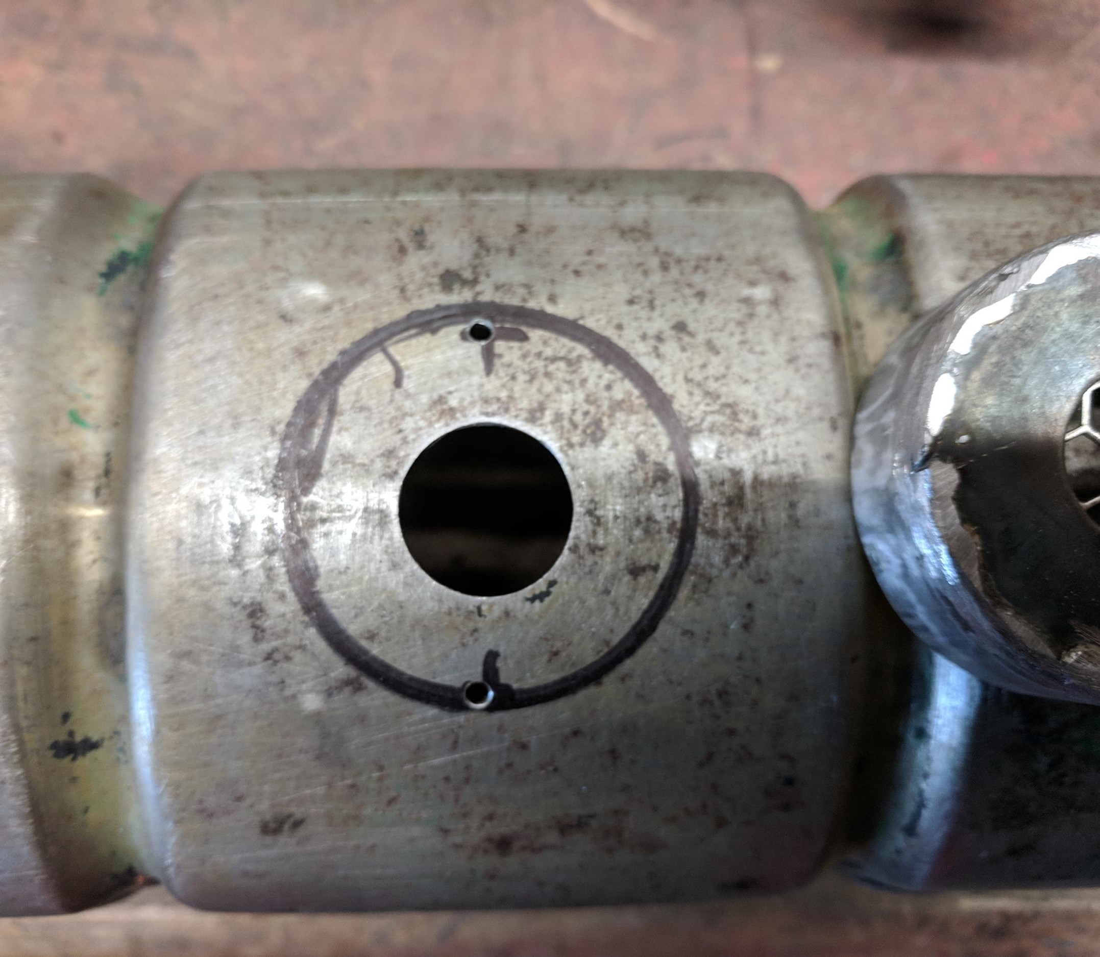
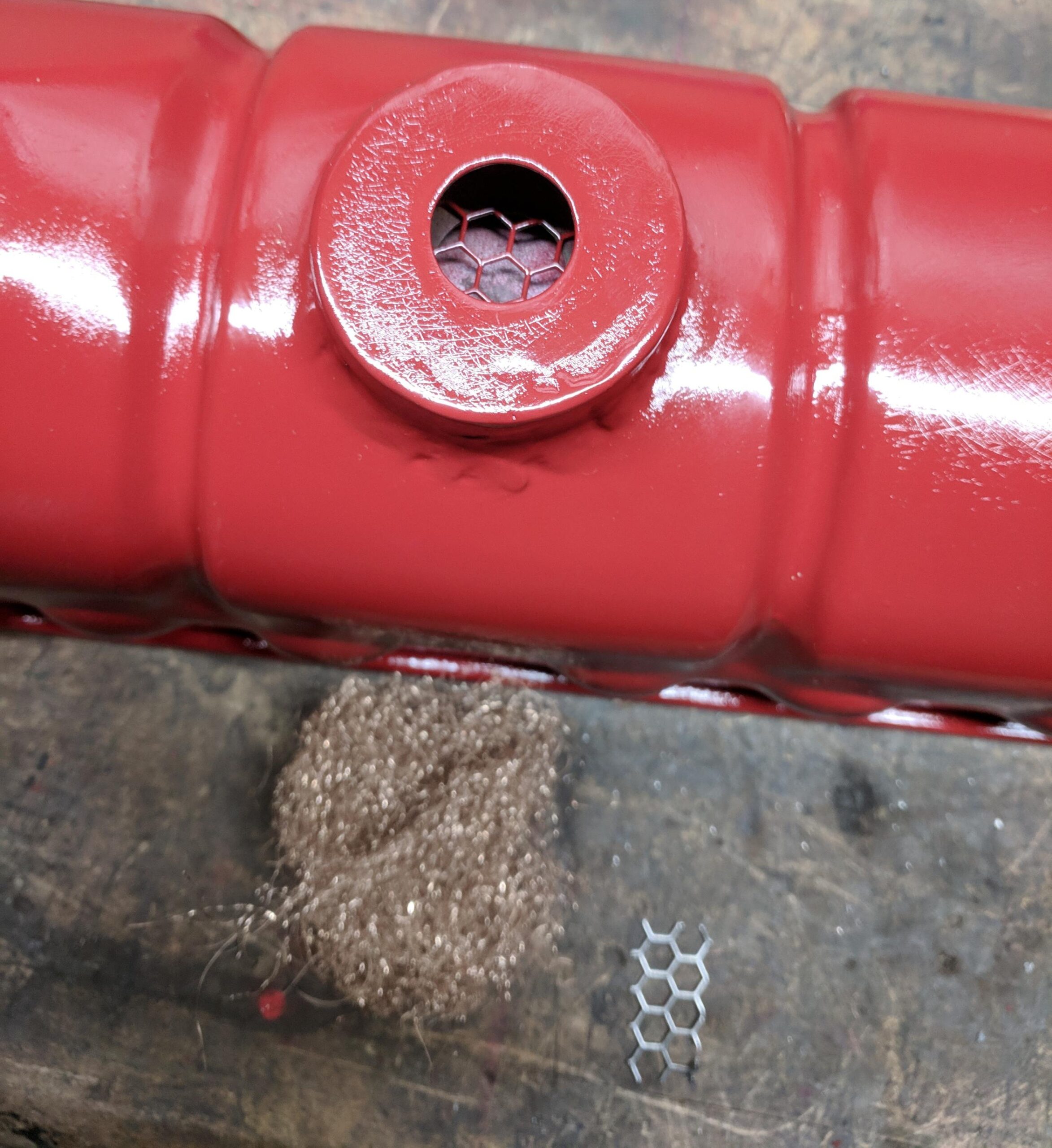
There’s a bit of 80%-open steel screen over the draft hole. Coarse bronze wool is very loosely packed in, then a rectangle of screen slips over it (see pic below). The chamber itself is a piece of 2″ steel tubing about 1″ tall at the highest point, 3/4″ at the lowest. It should be contoured to the top of the cover for a close fit. A top is welded on. The hole in the top is sized for a rubber PCV valve grommet. Actual size depends on where you source the valve and matching grommet, but usually 1″. JB Weld was smeared over the welds to seal any pinholes and the cover got painted, wool stuffed and screen and grommet inserted.
PCV valve
PCV valve flow rate is an esoteric and mystical subject, I assume, because there seems to be zero information available. I stood in the back of an Autozone, gently lifting the business end of each valve out of it’s container and sucking on it to guesstimate relative flow rates (“a lot” … “not much”, etc.). Looking like a crazy person for science… I’d made a list of candidate part numbers via images on web search and via my rigorous scientificalish characterization process above determined that the valve for a 1980 Honda Civic had the highest restriction and the right physical form factor. The valve has the pleasant part number of PCV1234. Common as dirt and very cheap.
As an aside, using engine vacuum as the source of air movement in the crankcase seems like a primitive holdover from the 1950s. A better system would be a dedicated pump and separators. Then actual gases, minus even water, would be a no-brainer to return to engine intake. There are electric PCV systems available, mostly for drag racing, and expensive. Some use a less expensive Delco or Ford pump, but it’s unclear how long such a pump would last under continuous operation. In the original application they only run a few seconds at a time. I don’t know what the original purpose is, probably to evacuate the crankcase until the engine is up and running for a minor emissions reduction at start-up.
Oil filler cap and dipstick
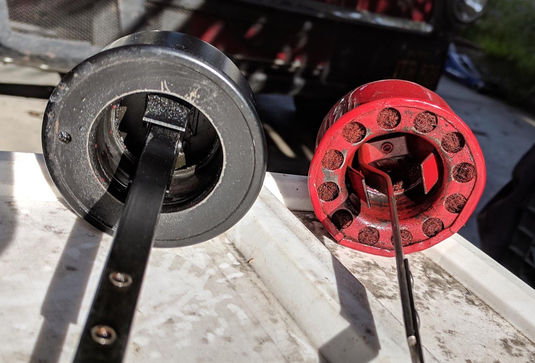
For a real PCV system the closed 1965 filler cap is best. It doesn’t have the large area vents and steel wool that was necessary for low restriction with the old road draft system (the cap was retained in most 195.6 PCV systems until 1965).
With positive ventilation, the (reduced) flow through the unvented cap will be fine. It also means when shut off, oil mists won’t waft out the cap all over the engine compartment. With adequate ventilation, that won’t matter. In the photo below a 65 cap is on the left, 63 on the right. Earlier models (and 64) use the 63 style cap (L-head and OHV engines). With a little work the early model cap can be sealed like the 65.
Demist-can PCV
This was the prototype for the velocity-can cover. It worked OK, it’s just ugly. After the first pass at valve cover PCV, I went back to a side-cover draw but with a special can between side cover and PCV valve. The hose from the side cover feeds the bottom of the can, the valve in a grommet on top. Inside are two perforated separators and coarse bronze wool.
The operation of the can isn’t immediately obvious — it is a widening of the hose to drop velocity, it is not a catch can. Whatever the air flow (fractional CFM) is inside that half-inch hose, it is fast enough to keep oil mist in suspension. The same volume of gas in a three-inch hose is far, far slower; this allows mist to fall out, and condense/collect, onto the bronze wool. This system works great. Oil that condenses in the can drains/dribbles back into the side cover, and air out the top is nearly dry.
This system has worked well for half a year, but it’s ugly and inconvenient under the hood. The velocity chamber solved the basic problem. While it’s more work, I like the look of it better and it doesn’t take any room under the hood — something in short supply in the 58-63 Americans.
Website contents, unless otherwise specified, © 2026 by Tom Jennings and Frank Swygert. Permission is granted for personal use with no remuneration. Corporations or any legal organization or their agents (employees or consultants or other relationships) expressly prohibited without written permission.